
As mentioned in the Introduction, a CGNS file is organized into a set of "nodes" in a tree-like structure, in much the same way as directories are organized in the UNIX environment. Each node is identified by both a label and a name. Most node labels are given by a series of characters followed by "_t". There are generally very strict rules governing the labeling conventions in a CGNS file. Node names are sometimes user-defined, but sometimes must also follow strict naming conventions. The label identifies a "type." For example, Zone_t identifies a Zone-type node, and DataArray_t identifies a type of node that contains a data array. The name identifies a specific instance of the particular node type. For example, Density is the name of a node of type DataArray_t that contains an array of densities.
As you become more familiar with how CGNS files are organized, you will notice that, generally, the higher you are in the CGNS hierarchy, the more important the label is (names tend to be user-defined); whereas the lower you are in the hierarchy, the more important the name is. This convention arises because at the higher levels, the broader categories are established, and are used to determine "where to go" in the hierarchy. At the lower levels, the category becomes less important because this is the region where you are searching for specific items.
Throughout the remainder of this first section, we will primarily be referring to the nodes by their label, because we are focusing on the "big picture." In later sections, as we get into specific examples, both names and labels will be referred to.
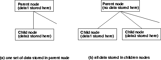
It is important to note at this point that the SIDS document specifies the layout of the CGNS file, in terms of parents and children. However, when a given piece of information is listed as being "under" a node, there are actually two possibilities: the information can be stored as data in the current node, or it can be stored as data in or under a separate child node. This distinction is illustrated in the figure below. The SIDS File Mapping Manual determines which of the two possibilities are used for each situation, and must always be consulted along with the SIDS document. Throughout the remainder of this section, the location of information (whether as data or as a separate child node) will always be explicitly specified, according to the SIDS File Mapping document.
The remainder of this section attempts to summarize the most important and most commonly-used aspects of the SIDS. It does not cover all possible nodes or situations. It is intended as a general overview only. It is also likely that future extensions to the SIDS will add additional capabilities beyond what we cover here.
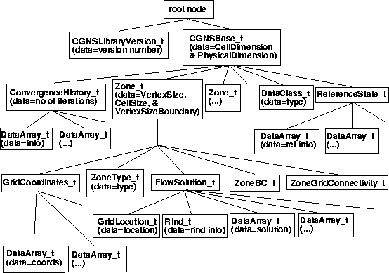
The top, or entry-level, of the CGNS file is always what is referred to as the "root node." Children to be found directly under this node are the node CGNSLibraryVersion_t and one or more CGNSBase_t nodes. The CGNSLibraryVersion_t node has, as its data, the version (release) number of the CGNS standard as defined by the SIDS. The CGNSBase_t node represents the top level for a given database, or "case." Most CGNS files will only have one CGNSBase_t node, although the SIDS allows for any number in order to remain extensible and to allow for the possibility of having more than one "case" in a single file. Here, the definition of "case" is left open. For the remainder of this section, we assume that there is only one CGNSBase_t node within a given CGNS file.
The CGNSBase_t node may have, as its children, the following nodes: Zone_t, ConvergenceHistory_t, BaseIterativeData_t, SimulationType_t, Family_t, IntegralData_t, DataClass_t, FlowEquationSet_t, DimensionalUnits_t, ReferenceState_t, Axisymmetry_t, RotatingCoordinates_t, Gravity_t, UserDefinedData_t,and Descriptor_t.
The Zone_t node gives information about a particular zone of the grid; most of the data in the CGNS file is usually found under this node. Any number of Zone_t nodes is allowed at this level. Its children will be described in greater detail below. ConvergenceHistory_t contains solution history information typically output by many CFD codes, such as residual, lift, drag, etc. as a function of iteration number. By convention, its name is GlobalConvergenceHistory. A ConvergenceHistory_t node can exist under the Zone_t node as well, but there, its name is by convention ZoneConvergenceHistory. BaseIterativeData_t stores information relating to the times and/or iteration numbers for a database in which flow solutions and/or grids at multiple times are stored. SimulationType_t describes the type of simulation stored (i.e., TimeAccurate or NonTimeAccurate). Family_t is generally used to tie the grid to geometric CAD data, or to link certain entities together as a common part (e.g., "wing," "strut," etc.). Any number of Family_t nodes is allowed. Axisymmetry_t, RotatingCoordinates_t, and Gravity_t are used for specific situations; details can be found in the SIDS.
The remaining nodes allowed under CGNSBase_t are somewhat more generic, and can exist at other levels in the hierarchy beside this one. They are briefly described here. IntegralData_t is a "catch-all" node for storing any desired sets of generic data. Any number of IntegralData_t nodes is allowed at this level. DataClass_t (which, by convention, has the name DataClass) indicates the form that the data in the CGNSBase_t is stored, for example: Dimensional, NormalizedByDimensional, or NormalizedByUnknownDimensional. FlowEquationSet_t (which, by convention, has the name FlowEquationSet) defines the equations used in the CFD simulation. DimensionalUnits_t (which, by convention, has the name DimensionalUnits) defines the dimensional units used (if any). ReferenceState_t (which, by convention, has the name ReferenceState) defines a reference state. This node is where quantities such as Reynolds number, Mach number, and other reference quantities that define the flow field conditions and/or the nondimensionalizations are stored. UserDefinedData_t is used to store user-defined data that is (by definition) not part of the SIDS standard. Finally, Descriptor_t is used to store descriptor strings. Any number of Descriptor_t nodes is allowed at this level.
The data stored within the CGNSBase_t node itself are the CellDimension and the PhysicalDimension. The CellDimension is the dimensionality of the cells in the mesh (e.g., 3 for volume cell, 2 for face cell). The PhysicalDimension is the number of coordinates required to define a node position (e.g., 1 for 1-D, 2 for 2-D, 3 for 3-D). The index dimension, which is the number of different indices required to reference a node (e.g., 1=i, 2=i,j, 3=i,j,k), is not stored, but can be determined for each zone based on its type (Structured or Unstructured). If Structured, the index dimension is the same as CellDimension. If Unstructured, the index dimension is 1.
Much information can be stored under Zone_t. Because this is an overview, we do not go through it all here. Instead, we only highlight the features that most users are likely to use. ZoneType_t (which, by convention, has the name ZoneType) stores the name Structured or Unstructured. GridCoordinates_t is the parent node of the grid coordinates arrays, such as CoordinateX, CoordinateY, and CoordinateZ. Any number of GridCoordinates_t nodes are allowed at this level (to handle the case of deforming grids). By convention, the original grid coordinates has the name GridCoordinates. FlowSolution_t stores under it nodes which contain the flow solution; for example, Density, VelocityX, VelocityY, VelocityZ, and Pressure. It also gives the location at which the solution is stored (e.g., CellCenter, Vertex), and includes the possibility for including Rind (ghost cell or ghost point) information. Any number of FlowSolution_t nodes are allowed at this level. The Elements_t data structure holds unstructured element data such as connectivity, neighbors, etc. Any number of Elements_t nodes are allowed at this level. ZoneIterativeData_t stores information necessary for a database in which flow solutions at multiple times are stored. Other important nodes under Zone_t are ZoneBC_t (which, by convention, has the name ZoneBC) and ZoneGridConnectivity_t (which, by convention, has the name ZoneGridConnectivity). These store the boundary conditions and the grid connectivity information, respectively. More will be said about these nodes later.
The data stored within the Zone_t node itself are the VertexSize, the CellSize, and the VertexSizeBoundary. These are dimensioned by the index dimension, and give the number of vertices, the number of cells, and the number of boundary vertices (used for sorted elements in unstructured zones only), respectively.
An important point to note here is that the API sorts the Zone_t nodes alphanumerically according to their name when it reads them. This was deemed necessary because most CFD codes currently perform operations on the zones of multiple-zone grids in a certain order. To duplicate existing non-CGNS applications, it is necessary to insure that zones can be read in the desired sequence. (the database manager may not retrieve data in the same order in which it was stored, so the API reader for zones was built to do this.) Hence, when naming zones, the user should make sure they are named alphanumerically (if an ordering is desired).
For example, the naming convention ZoneN, where N is the zone number, is alphanumeric only up to Zone9. Zone10 through Zone19 would get sorted between Zone1 and Zone2, and so on. Spaces are allowed in names, so Zone N, with two spaces, (e.g., Zone 1, Zone 2,... Zone 99, Zone100,...) is alphanumeric up to Zone999. Other zone naming conventions are certainly possible, and are completely up to the user to define appropriately.
A summary graphic of the overall layout of a typical CGNS file is given below. This figure shows the hierarchical data structure, and the relative locations of the nodes. It also indicates (informally) what data, if any, is stored within each node.
Most of the actual data is at the lower levels of the CGNS hierarchy. We do not go into great detail here; the examples in the main body of this document serve as instruction for this. However, there are several general items of importance related to the storage of data that are appropriate to mention here.
Many specific items, variables, and conditions that relate to CFD data are specified in the SIDS. These are standardized names that must be used in order that other users will understand what is in your CGNS file. For example, the static density must be called Density. Any other name may not be recognized by other users. In fact, if another application code expects "Density," but you name it "density" (lower case "d"), then chances are the other code's search will fail.
Naturally, the items listed in the SIDS cannot cover all possible items required by users. Hence, the SIDS allows for the use of the type UserDefinedData_t for any special type not covered. For example, there are currently only a limited number of defined names for turbulence models in the SIDS (e.g., OneEquation_SpalartAllmaras). As everyone knows, there are a huge number of turbulence models and turbulence model variants that exist, so that the SIDS cannot hope to define standardized names for all of them. The type UserDefinedData_t covers this situation.
When UserDefinedData_t is used, however, the user runs the risk that others will be unable to interpret the CGNS file. We therefore recommend that whenever a UserDefinedData_t type is unavoidable, the user also include a companion Descriptor_t node to specify what was done.
It is possible that, if certain items are found to be used more heavily as time goes on, that standardized names may be created and added to the SIDS in the future.
The boundary conditions hierarchical structure in CGNS can appear to be somewhat daunting at first. Because the CGNS team decided to make the boundary condition information as descriptive as possible and easily extensible to complex situations, there are many layers possible in the hierarchy, and the usage rules can become complex.
However, the SIDS allows for use of simplified versions of the ZoneBC_t node, which are easier to understand and adopt. Essentially, the simplified versions "cut off" the hierarchy at a higher level than the full-blown SIDS boundary condition description. The implication of this is that application codes that use a simplified version must interpret what is meant by each particular boundary condition type, without the help of the CGNS file.
For example, the boundary condition type BCFarfield indicates a boundary condition applied to a far field boundary. Most CFD codes have this type, which performs different functions depending upon whether the local flow field is inflow or outflow, subsonic or supersonic. The full-blown SIDS description of BCFarfield attempts to describe in some detail the methodology involved in this boundary condition. However, if the user chooses to use the minimal "cut off" version, the only information regarding the function of the boundary condition that is stored in the CGNS file is the name BCFarfield. An application code must determine from this name alone what is meant.
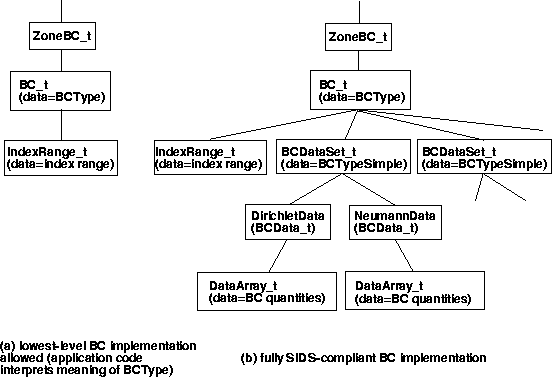
Example hierarchical structures for both the simplest implementation as well as the full-blown implementation of the ZoneBC_t node are shown in the above figure. (These hierarchies make use of an IndexRange_t node. It is also possible to use an IndexArray_t, which gives a complete list of boundary indices or elements, rather than a range.) Note that an intermediate structure, where BCDataSet_t and BCTypeSimple_t are both given but DirichletData and NeumannData are not, is also allowed.
Many boundary condition types are currently defined in the SIDS, but they by no means cover all possible boundary conditions. The type UserDefinedData_t can be used for any special type not covered that the user finds impossible to describe using the existing SIDS. When UserDefinedData_t is used, a companion descriptor node is helpful to describe what was done.
It is often desirable to specify zone connectivity information when parts of a zone connect with parts of another zone or itself. The connectivity information tells how zones fit together or how a zone twists to reconnect with itself; the information is needed by most CFD flow solvers.
There are three types of connectivity that can occur: point-by-point, patched, and overset. The point-by-point, or 1-to-1, type occurs when the edges of zones abut, and grid vertices from one patch exactly correspond with grid vertices from the other, with no points missing a partner. The patched type occurs when the edges of zones abut, but there is not a correspondence of the points, or they are not partnered with another point. The overset type occurs when zones overlap one another (or a zone overlaps itself).
The SIDS allows for the specification of each of these types of zone connectivity under the ZoneGridConnectivity_t node. All three types can be implemented through the general GridConnectivity_t subnode (overset also requires the use of OversetHoles_t nodes). However, the 1-to-1 type can also utilize, in certain circumstances, the more specific GridConnectivity1to1_t subnode.
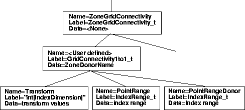
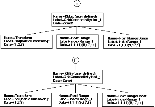
The following figure shows a sample hierarchy starting at the ZoneGridConnectivity_t node, for a 1-to-1 type of interface using a GridConnectivity1to1_t subnode. Note in this figure that we now list the name, label, and data within each node. For this structure, the naming convention at the bottom level is particularly important, and is actually more descriptive than the labels. In fact, the label for the Transform node is very strange, and does not even follow the usual "_t" convention. As can be seen in the figure, multiple nodes are allowed under the ZoneGridConnectivity_t node. These can be any combination of GridConnectivity1to1_t, GridConnectivity_t, OversetHoles_t, or Descriptor_t nodes.
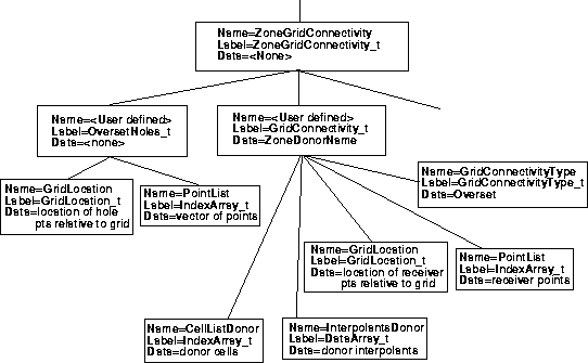
A sample hierarchy (again starting at the ZoneGridConnectivity_t node) is shown in the next figure for an overset interface using a GridConnectivity_t subnode. The case for a patched interface would look the same, except there would be no OversetHoles_t node or its children and GridConnectivityType would be Abutting. Note that CellListDonor and InterpolantsDonor are used for patched or overset interfaces. (PointListDonor can be used in their place if the interface is 1-to-1.) See the SIDS document and the file mapping manual for details.)
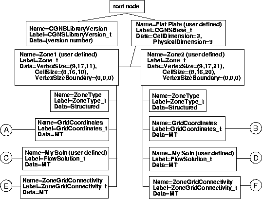
The following is an example for a structured grid. It corresponds with the "1-to-1 Abutting of Complete Faces" example in the SIDS document. It is a 3-D two-zone case, where the two zones are connected in a 1-to-1 fashion at one of each of their faces. Zone 1 is 9 × 17 × 11 and zone 2 is 9 × 17 × 21. The k-max face of zone 1 abuts the k-min face of zone 2.
The hierarchy is shown in the following four figures. Only directly relevant parts of the hierarchy are shown here for clarity. For example, DataClass_t, ReferenceState_t, ConvergenceHistory_t, FlowEquationSet_t, and ZoneBC_t have all been left off. However, these (and other) items are not required, and the figure still represents a valid SIDS-compliant CGNS file. Note that a data type of MT indicates that there is no data stored in the node.
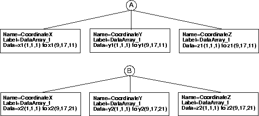
In this example, the flow solution in zone 1 is given at cell centers, whereas the flow solution in zone 2 is given at the vertices (see the FlowSolution_t figure). In other words, the zone 1 solution points do not correspond with the grid points (as they do in zone 2). They are defined within the volumes surrounded by the grid points. This example is constructed this way for the purpose of illustration, but it is unusual; typically one would use only a single flow solution data location for the entire file.
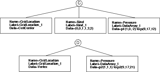
This example also illustrates the use of the Rind_t node, and how it affects the data arrays under a FlowSolution_t. A rind node under FlowSolution_t is used to indicate that the flow solution is outputting additional rind or "ghost" data outside one or more boundaries of the zone. (A rind node can also be used under GridCoordinates_t and DiscreteData_t.) See the SIDS document for a more complete description. In zone 1 in this example, there are no additional ghost cell data in the i-direction, there is one ghost cell next to each of j-min and j-max, and there are 3 ghost cells next to k-min and 2 next to k-max. (Admittedly, this example is very contrived - most applications would be more consistent in their use of rind cells.) Because of the rind cells, the i, j, and k ranges of all flow solution data arrays in zone 1 are extended appropriately.
It is very important for the user to realize that including rind cells affects how the data is stored in the DataArray_t's. In other words, when reading a CGNS file one cannot ignore Rind_t nodes if they are present, and attempting to read the DataArray_t's using unmodified VertexSize or CellSize dimensions will result in the retrieval of nonsensical data.
Note that the SIDS specifies many defaults. For example, the default Transform values are (1,2,3), and the default GridLocation is Vertex. Hence, the nodes that contain these particular values in the example are not strictly necessary. The API sometimes leaves out default information.
Another important fact is illustrated in this example. When the names of a type of node (of given label) are user defined, the names must be different if they have the same parent node. For example, the two Zone_t nodes in this example must have different names (recall the earlier discussion of zone naming). However, if they are located in different places in the hierarchy, two nodes with the same label can have the same name. For example, both of the FlowSolution_t nodes, located in two different zones, have been given the same user-defined name: "My Soln" in the example.
Finally, although the ZoneBC_t nodes were not included in this example, note that if they were, they should describe the boundary conditions on all boundary faces except the k-max face of zone 1 and the k-min face of zone 2. These two faces would not be included in the boundary conditions because they are already defined as connectivity interfaces.