

This section defines structures for describing multizone interface connectivity for 1-to-1 abutting, mismatched abutting, and overset type interfaces. All interface connectivity information pertaining to a given zone is grouped together in a ZoneGridConnectivity_t structure entity; this in turn is contained in a zone structure entity.
Before presentation of the structure definitions, a few design features require comment. All indices used to describe interfaces are the dimensionality (IndexDimension) of the grid, even when they are used to describe lower-dimensional zonal boundaries for abutting interfaces. The alternative for structured zones that was not chosen is to use lower-dimensional indices for lower-dimensional interfaces (e.g., for a 3-D grid, use two-dimensional indices for describing grid planes that are interfaces). Both alternatives offer trade-offs. The lower-dimensional indices require cyclic notation conventions and additional identification of face location; whereas, full-dimensional indices result in one redundant index component when describing points along a grid plane. We decided that full-dimensional indices would be more usable and less error prone in actual implementation.
A major consequence of this decision is that connectivity information for describing mismatched abutting interfaces and overset interfaces can be merged into a single structure, GridConnectivity_t. In fact, this single structure type can be used to describe all zonal interfaces.
A second design choice was to duplicate all 1-to-1 abutting interface information within the CGNS database. It is possible to describe a given 1-to-1 interface with a single set of connectivity data. In contrast, mismatched and overset interfaces require different connectivity information when the roles of receiver and donor zones are interchanged. Therefore, a given mismatched or overset interface requires two sets of connectivity data within the database. The decision to force two sets of connectivity data (one contained in each of the Zone_t entities for the two adjacent zones)for each 1-to-1 interface makes the connectivity structures for all interface types look and function similarly. It also fits better with the zone-by-zone hierarchy chosen for the CGNS database. The minor penalty in data duplication was deemed worth the advantages gained.
Note that it is a CGNS design intent that a given zone boundary segment or location should at most be defined (or covered) by either a boundary condition or a multizone interface connectivity, but not by both.
All multizone interface grid connectivity information pertaining to a given zone is contained in the ZoneGridConnectivity_t structure. This includes abutting interfaces (1-to-1 and general mismatched), overset-grid interfaces, and overset-grid holes.
  ZoneGridConnectivity_t< int IndexDimension, int CellDimension > :=
    {
    List( Descriptor_t Descriptor1 ... DescriptorN ) ;                 (o)

    List( GridConnectivity1to1_t<IndexDimension>
          GridConnectivity1to11 ... GridConnectivity1to1N ) ;          (o)

    List( GridConnectivity_t<IndexDimension, CellDimension>
          GridConnectivity1 ... GridConnectivityN ) ;                  (o)

    List( OversetHoles_t<IndexDimension>
          OversetHoles1 ... OversetHolesN ) ;                          (o)

    List( UserDefinedData_t UserDefinedData1 ... UserDefinedDataN ) ;  (o)
    } ;
Notes
ZoneGridConnectivity_t requires two structure parameters, IndexDimension, which is passed onto all connectivity substructures, and CellDimension, which is passed to GridConnectivity_t only.
Connectivity information for 1-to-1 or matched multizone interfaces is contained in the GridConnectivity1to1_t structure. Abutting and overset connectivity is contained in the GridConnectivity_t structure, and overset-grid holes are identified in the OversetHoles_t structure.
The UserDefinedData_t data structure allows arbitrary user-defined data to be stored in Descriptor_t and DataArray_t children without the restrictions or implicit meanings imposed on these node types at other node locations.
GridConnectivity1to1_t only applies to structured zones interfacing with structured donors and whose interface is a logically rectangular region. It contains connectivity information for a multizone interface patch that is abutting with 1-to-1 matching between adjacent zone indices (also referred to as C0 connectivity). An interface patch is the subrange of the face of a zone that touches one and only one other zone. This structure identifies the subrange of indices for the two adjacent zones that make up the interface and gives an index transformation from one zone to the other. It also identifies the name of the adjacent zone.
All the interface patches for a given zone are contained in the ZoneGridConnectivity_t entity for that zone. If a face of a zone touches several other zones (say N), then N different instances of the GridConnectivity1to1_t structure must be included in the zone to describe each separate interface patch. This convention requires that a single interface patch be described twice in the database - once for each adjacent zone.
  GridConnectivity1to1_t< int IndexDimension > :=
    {
    List( Descriptor_t Descriptor1 ... DescriptorN ) ;                 (o)

    int[IndexDimension] Transform ;                                    (o/d)

    IndexRange_t<IndexDimension> PointRange ;                          (r)
    IndexRange_t<IndexDimension> PointRangeDonor ;                     (r)

    Identifier(Zone_t) ZoneDonorName ;                                 (r)

    GridConnectivityProperty_t GridConnectivityProperty ;              (o)

    List( UserDefinedData_t UserDefinedData1 ... UserDefinedDataN ) ;  (o)

    int Ordinal ;                                                      (o)
    } ;
Notes
PointRange contains the subrange of indices that makes up the interface patch in the current zone (i.e., that Zone_t entity that contains the given instance of GridConnectivity1to1_t). PointRangeDonor contains the interface patch subrange of indices for the adjacent zone (whose identifier is given by ZoneDonorName). By convention the indices contained in PointRange and PointRangeDonor refer to vertices.
Transform contains a short-hand notation for the transformation matrix describing the relation between indices of the two adjacent zones. The transformation matrix itself has rank IndexDimension and contains elements +1, −1 and 0; it is orthonormal and its inverse is its transpose. The transformation matrix (T) works as follows: If Index1 and Index2 are the indices of a given point on the interface, where Index1 is in the current zone and Index2 is in the adjacent zone, then their relationship is,
        Index2 = T.(Index1 - Begin1) + Begin2

        Index1 = Transpose[T].(Index2 - Begin2) + Begin1
where the "." notation indicates matrix-vector multiply.
Begin1 and End1 are the subrange indices contained
in PointRange, and Begin2 and End2 are the
subrange indices contained in PointRangeDonor.
The short-hand notation used in Transform is as follows: Each
element shows the image in the adjacent zone's face of a positive index
increment in the current zone's face.
The first element is the image of a positive increment in i; the
second element is the image of an increment in j; and the third
(in 3-D) is the image of an increment in k on the current zone's
face.
For 3-D, the transformation matrix T is constructed from
Transform =
[±a, ±b, ±c]
as follows:

For example, Transform = [−2, +3, +1] gives the
transformation matrix,
![Transformation matrix for Transform = [-2, +3, +1]](cnct.eqs/Texample.gif)
For establishing relationships between adjacent and current zone indices lying on the interface itself, one of the elements of Transform is superfluous since one component of both interface indices remains constant. It is therefore acceptable to set that element of Transform to zero.
If the transformation matrix is used for continuation of computational coordinates into the adjacent zone (e.g., to find the location of a rind point in the adjacent zone), then all elements of Transform are needed. If the above mentioned superfluous element is set to zero, it can be easily regenerated from PointRange and PointRangeDonor and the grid sizes of the two zones. This is done by determining the faces represented by PointRange and PointRangeDonor (i.e., i-min, i-max, j-min, etc.). If one is a minimum face and the other a maximum face, then the sign of the missing element in Transform is "+", and the value of the missing element in the transformation matrix (T) is +1. If the faces are both minimums or are both maximums, the sign is "−". Next, the position and magnitude of the element in Transform, and hence the row and column in the transformation matrix, is given by the combinations of i, j and k faces for the two. For example, if PointRange represents a j-min or j-max face and PointRangeDonor represents an i-min or i-max face, then the missing element's position in Transform is 2 and its magnitude is 1 (i.e., Transform = [*, ±1, *]).
Note also that the transform matrix and the two index pairs overspecify the interface patch. For example, End2 can be obtained from Transform, Begin1, End1 and Begin2.
A GridConnectivityProperty_t data structure may be used to record special properties associated with particular connectivity patches, such as a periodic interface, or an interface where data is to be averaged in some way.
The UserDefinedData_t data structure allows arbitrary user-defined data to be stored in Descriptor_t and DataArray_t children without the restrictions or implicit meanings imposed on these node types at other node locations.
Ordinal is user-defined and has no restrictions on the values that it can contain. It is included for backward compatibility to assist implementation of the CGNS system into applications whose I/O depends heavily on the numbering of zone interfaces. Since there are no restrictions on the values contained in Ordinal (or that Ordinal is even provided), there is no guarantee that the interfaces in an existing CGNS database will have sequential values from 1 to N without holes or repetitions. Use of Ordinal is discouraged and is on a user-beware basis.
This section contains two examples of structure entities for describing the connectivity for structured-zone 1-to-1 abutting multizone interfaces. The Structured Two-Zone Flat Plate Example contains additional examples of 1-to-1 interfaces.
Two zones have the same orientation; zone 1 is 9 × 17 × 11 and zone 2 is 9 × 17 × 21. The k-max face of zone 1 abuts the k-min face of zone 2. Contained in the structure entities of zone 1 is the following interface structure:
  GridConnectivity1to1_t<3> Zone1/ZoneGridConnectivity/KMax =
    {{
    int[3] Transform = [1,2,3] ;
    IndexRange_t<3> PointRange =
      {{
      int[3] Begin = [1,1,11] ;
      int[3] End   = [9,17,11] ;
      }} ;
    IndexRange_t<3> PointRangeDonor =
      {{
      int[3] Begin = [1,1,1] ;
      int[3] End   = [9,17,1] ;
      }} ;
    Identifier(Zone_t) ZoneDonorName = Zone2 ;
    }} ;
Contained in the structure entities of zone 2 is the following:
  GridConnectivity1to1_t<3> Zone2/ZoneGridConnectivity/KMin =
    {{
    int[3] Transform = [1,2,3] ;
    IndexRange_t<3> PointRange =
      {{
      int[3] Begin = [1,1,1] ;
      int[3] End   = [9,17,1] ;
      }} ;
    IndexRange_t<3> PointRangeDonor =
      {{
      int[3] Begin = [1,1,11] ;
      int[3] End   = [9,17,11] ;
      }} ;
    Identifier(Zone_t) ZoneDonorName = Zone1 ;
    }} ;
This example assumes zones 1 and 2 have the identifiers Zone1
and Zone2, respectively.

The above figure shows a more complex 1-to-1 abutting interface, where the entire j-max face of zone 2 coincides with a subset of the i-max face of zone 1. This situation would result in the following connectivity structures:
  GridConnectivity1to1_t<3> Zone1/ZoneGridConnectivity/IMax =
    {{
    int[3] Transform = [-2,-1,-3] ;
    IndexRange_t<3> PointRange =
      {{
      int[3] Begin = [17,3,1] ;
      int[3] End   = [17,9,5] ;
      }} ;
    IndexRange_t<3> PointRangeDonor =
      {{
      int[3] Begin = [7,9,5] ;
      int[3] End   = [1,9,1] ;
      }} ;
    Identifier(Zone_t) ZoneDonorName = Zone2 ;
    }} ;
  GridConnectivity1to1_t<3> Zone2/ZoneGridConnectivity/JMax =
    {{
    int[3] Transform = [-2,-1,-3] ;
    IndexRange_t<3> PointRange =
      {{
      int[3] Begin = [1,9,1] ;
      int[3] End   = [7,9,5] ;
      }} ;
    IndexRange_t<3> PointRangeDonor =
      {{
      int[3] Begin = [17,9,5] ;
      int[3] End   = [17,3,1] ;
      }} ;
    Identifier(Zone_t) ZoneDonorName = Zone1 ;
    }} ;
This example also assumes zones 1 and 2 have the identifiers Zone1 and Zone2, respectively. Note that the index transformation matrix for both this and the previous examples is symmetric; hence, the value of Transform is identical for both members of the interface pair. In general this will not always be the case.
GridConnectivity_t contains connectivity information for generalized multizone interfaces, and may be used for any mix of structured and unstructured zones. Its purpose is to describe mismatched-abutting and overset interfaces, but can also be used for 1-to-1 abutting interfaces.
For abutting interfaces that are not 1-to-1, also referred to as patched or mismatched, an interface patch is the subrange of the face of a zone that touches one and only one other zone. This structure identifies the subrange of indices (or array of indices) that make up the interface and gives their image in the adjacent (donor) zone. It also identifies the name of the adjacent zone. If a given face of a zone touches several (say N) adjacent zones, then N different instances of GridConnectivity_t are needed to describe all the interfaces. For a single abutting interface, two instances of GridConnectivity_t are needed in the database - one for each adjacent zone.
For overset interfaces, this structure identifies the fringe points of a given zone that lie in one and only one other zone. If the fringe points of a zone lie in several (say N) overlapping zones, then N different instances of GridConnectivity_t are needed to describe the overlaps. It is possible with overset grids that a single fringe point may actually lie in several overlapping zones (though in typical usage, linkage to only one of the overlapping zones is kept). There is no restriction against a given fringe point being contained within multiple instances of GridConnectivity_t; therefore, this structure allows the description of a single fringe point lying in several overlapping zones.
  GridConnectivityType_t := Enumeration(
    GridConnectivityTypeNull,
    GridConnectivityTypeUserDefined,
    Overset,
    Abutting,
    Abutting1to1 ) ;

  GridConnectivity_t< int IndexDimension, int CellDimension > :=
    {
    List( Descriptor_t Descriptor1 ... DescriptorN ) ;                 (o)

    GridConnectivityType_t GridConnectivityType ;                      (o/d)

    GridLocation_t GridLocation ;                                      (o/d)

    IndexRange_t<IndexDimension> PointRange ;                          (o:r)
    IndexArray_t<IndexDimension, PointListSize, int>  PointList ;      (r:o)
    IndexArray_t<IndexDimension, PointListSize, int>  PointListDonor ; (o)
    IndexArray_t<IndexDimension, PointListSize, int>  CellListDonor ;  (o)

    Identifier(Zone_t) ZoneDonorName ;                                 (r)

    DataArray_t <real, 2, [CellDimension, PointListSize]>
       InterpolantsDonor                                               (o)

    GridConnectivityProperty_t GridConnectivityProperty ;              (o)

    List( UserDefinedData_t UserDefinedData1 ... UserDefinedDataN ) ;  (o)

    int Ordinal ;                                                      (o)
    } ;
Notes
The type of multizone interface connectivity may be Overset, Abutting, or Abutting1to1. Overset refers to zones that overlap; for a 3-D configuration the overlap is a 3-D region. Abutting refers to zones that abut or touch, but do not overlap (other than the vertices and faces that make up the interface). Abutting1to1 is a special case of abutting interfaces where grid lines are continuous across the interface and all vertices on the interface are shared by the two adjacent zones.
The interface grid points within the receiver zone may be specified by PointRange if they constitute a logically rectangular region (e.g., an abutting interface where an entire face of the receiver zone abuts with a part of a face of the donor zone). In all other cases, PointList should be used to list the receiver-zone grid points making up the interface. For a structured-to-structured interface, all indices in PointRange or PointList should have one index element in common (see note 7).
GridLocation identifies the location of indices within the receiver zone described by PointRange or PointList. It also identifies the location of indices defined by PointListDonor in the donor zone. GridLocation does not apply to CellListDonor or InterpolantsDonor. The CellListDonor is always an index or indices that define a particular cell or element, while the InterpolantsDonor defines an interpolation value relative to the cell/element vertices. In other words, when using InterpolantsDonor, the interpolants are always given with respect to the vertices of the donor zone. InterpolantsDonor is currently only defined for structured grids and certain basic unstructured grid element types.
For structured grids, the interpolant value is given along each index direction, depending on the location within the cell. For example, if the point is located within the cell at a position 75% in the i-direction, 41% in the j-direction, and 20% in the k-direction, then InterpolantsDonor values (r, s, t) would be (0.75, 0.41, 0.20).
The interpolation function is a linear combination of the x,
y, and z values at the surrounding nodes:

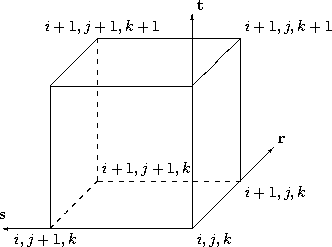
| Wi,j,k =
(1 − r)(1 − s)(1 − t) Wi+1,j,k = r(1 − s)(1 − t) Wi,j+1,k = (1 − r)s(1 − t) Wi,j,k+1 = (1 − r)(1 − s)t Wi+1,j+1,k = rs(1 − t) Wi+1,j,k+1 = r(1 − s)t Wi,j+1,k+1 = (1 − r)st Wi+1,j+1,k+1 = rst |
For unstructured grids, InterpolantsDonor is defined only for
the basic linear element types:
BAR_2,
TRI_3,
QUAD_4,
TETRA_4,
PYRA_5,
PENTA_6,
and HEXA_8.
The directionality for the r, s, and t interpolants
for the basic element types is defined as follows.
| BAR_2 | |||

| W1 = 1 − r W2 = r |
| TRI_3 | |||
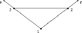
| W1 = 1 − r − s W2 = r W3 = s |
| QUAD_4 | |||
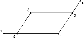
| W1 = (1 − r)(1 − s) W2 = r(1 − s) W3 = rs W4 = (1 − r)s |
| TETRA_4 | |||
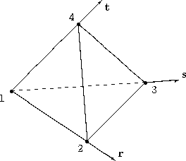
| W1 = 1 − r − s − t W2 = r W3 = s W4 = t |
| PYRA_5 | |||
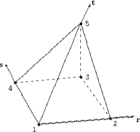
| W1 = (1 − r)(1 − s)(1 − t) W2 = r(1 − s)(1 − t) W3 = rs(1 − t) W4 = (1 − r)s(1 − t) W5 = t |
| PENTA_6 | |||
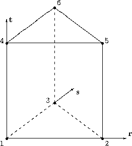
| W1 = (1 − r − s)(1 − t) W2 = r(1 − t) W3 = s(1 − t) W4 = (1 − r − s)t W5 = rt W6 = st |
| HEXA_8 | |||
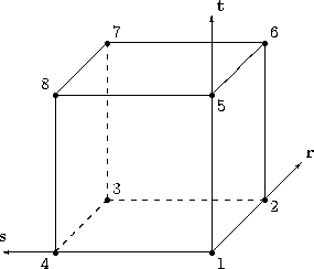
| W1 = (1 − r)(1 − s)(1 − t) W2 = r(1 − s)(1 − t) W3 = rs(1 − t) W4 = (1 − r)s(1 − t) W5 = (1 − r)(1 − s)t W6 = r(1 − s)t W7 = rst W8 = (1 − r)st |
PointListDonor may only be used when the interface is Abutting1to1. It contains the images of all the receiver-zone interface points in the donor zone. If the zone is structured, all indices in PointListDonor should have one index element in common.
For mismatched or overset interfaces, the zone connectivity donor information, when given, is defined using either the CellListDonor alone, or the combination of CellListDonor and InterpolantsDonor. CellListDonor contains the list of donor cells or elements in which each node of the receiver zone can be located. InterpolantsDonor contains the interpolation factors to locate the receiver nodes in the donor cells. InterpolantsDonor may be thought of as bi- or tri-linear interpolants (depending on CellDimension) in the cell of the donor zone.
A GridConnectivityProperty_t data structure may be used to record special properties associated with particular connectivity patches, such as a periodic interface, or an interface where data is to be averaged in some way.
The UserDefinedData_t data structure allows arbitrary user-defined data to be stored in Descriptor_t and DataArray_t children without the restrictions or implicit meanings imposed on these node types at other node locations.
Ordinal is user-defined and has no restrictions on the values that it can contain. It is included for backward compatibility to assist implementation of the CGNS system into applications whose I/O depends heavily on the numbering of zone interfaces. Since there are no restrictions on the values contained in Ordinal (or that Ordinal is even provided), there is no guarantee that the interfaces for a given zone in an existing CGNS database will have sequential values from 1 to N without holes or repetitions. Use of Ordinal is discouraged and is on a user-beware basis.
PointListDonor, CellListDonor, and InterpolantsDonor require the function PointListSize, to identify the length of the array. If PointRange is specified by GridConnectivity_t, then PointListSize is obtained from the number of grid points (inclusive) between the beginning and ending indices of PointRange. If PointList is specified by GridConnectivity_t, then PointListSize is actually a user input during creation of the database; it is the length of the array PointList whose elements are also user inputs (by "user" we mean the application code that is generating the CGNS database).
By definition, the PointList and PointListDonor arrays have the same size, and this size should be stored along with the arrays in their respective IndexArray_t structures. PointListSize was chosen to be a structure function, rather than a separate element of GridConnectivity_t for the following reasons: first, it is redundant if PointRange is specified; and second, it leads to redundant storage if PointList is specified, since the value of PointListSize is also stored within the PointList structure.
This situation has somewhat of a precedent within the SIDS definitions. The structure Descriptor_t contains a string of unspecified length. Yet in actual implementation, the (string) length is a function of the descriptor string itself and should be stored along with the string.
Say that you have a three-dimensional structured grid.
Assume that at the interface between two zones you have the following
situation.
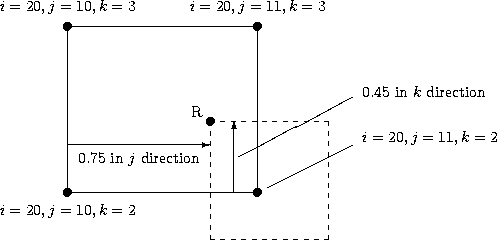
In this particular example, the patching occurs on a "plane". In other words, the two cells in 3-D have faces that abut in a 2-D sense. It is these faces that we are picturing here. The solid quadrilateral is the donor cell face, and the dashed quadrilateral is the position of the receiving cell face relative to the donor cell. Note that since this is a 2-D-type of abutting case, one of the indices (in this case i = 20, which represents imax) of the donor cell is constant. For this example, the point R of the receiver cell is located within the donor cell pictured, and we wish to give the CellListDonor and InterpolantsDonor for it.
Because this is a structured grid, the CellListDonor in this case is given by
CellListDonor = (19, 10, 2)
Here, we are using the Structured Grid Notation and Indexing Conventions that say cell centers, face centers, and edge centers are indexed by the minimum i, j, and k indices of the connecting vertices.
The InterpolantsDonor defines an interpolation value relative to the cell/element vertices. In this case, say that the point R is located 0.75 along the j-index direction and 0.45 along the k-index direction. (It also lies on the i = 20, or imax face.) Thus, in this example:
InterpolantsDonor = (1.0, 0.75, 0.45)Note that if the donor zone was instead located on an i = 1 (imin face), then the CellListDonor would be (1, 10, 2) and the InterpolantsDonor would be (0.0, 0.75, 0.45).
As a second example, assume that you have the same setup as before, but
now with a three-dimensional unstructured grid.
In this case, we no longer have a 3-D array of indices defining
coordinate directions.
Instead, we simply have a 1-D list of indices as well as a list of
volume (and possibly face) elements composed of those indices.
In this example we again are assuming the two zones abut in a 2-D sense.
We now have the choice of describing the donor in terms of its volume
element or its boundary (face) element, if available.
Here in this example, we use the volume element.
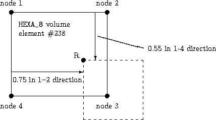
The HEXA_8 volume element has been appropriately numbered, using the Unstructured Grid Element Numbering Conventions. In this example, it is the 1-2-3-4 face of the volumetric element that is abutting with the other zone (but it could be any of its six faces)
The CellListDonor in this case is simply given by
CellListDonor = (238)Using the convention established above for HEXA_8 elements, the InterpolantsDonor would be
InterpolantsDonor = (0.75, 0.55, 0.0)
As a third example, assume that you have two zones in a
three-dimensional unstructured grid with triangles and quadrilaterals at
its boundaries.
Here the current zone (made up of quadrilateral faces) is abutting the
donor zone (made up of triangular faces) in a 2-D sense.
We again have the choice of describing the donor in terms of its volume
element or its boundary (face) element.
Here in this example, we use the face element.
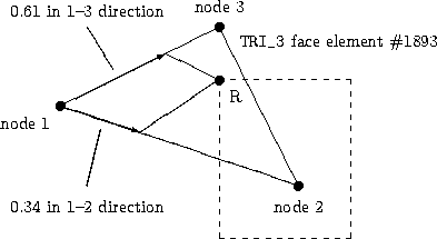
The CellListDonor in this case is simply given by
CellListDonor = (1893)Using the convention established above for TRI_3 elements, the InterpolantsDonor would be:
InterpolantsDonor = (0.34, 0.61)In this case the third dimension of the InterpolantsDonor (although present) is not used, because by default the interpolation is only two-dimensional in the 2-D plane of the donor face.
GridConnectivityProperty_t allows the recording of special properties associated with particular connectivity patches. At the current time, only two properties (Periodic_t and AverageInterface_t) are included, but extensions involving other properties may be implemented as additional nodes under GridConnectivityProperty_t in the future.
  GridConnectivityProperty_t :=
    {
    List( Descriptor_t  Descriptor1 ... DescriptorN ) ;                (o)

    Periodic_t Periodic ;                                              (o)

    AverageInterface_t AverageInterface ;                              (o)

    List( UserDefinedData_t UserDefinedData1 ... UserDefinedDataN ) ;  (o)
    } ;
Notes
The Periodic_t and AverageInterface_t data structures may be used to record properties associated with periodic interfaces, or interfaces where data is to be averaged in some way, respectively.
The UserDefinedData_t data structure allows arbitrary user-defined data to be stored in Descriptor_t and DataArray_t children without the restrictions or implicit meanings imposed on these node types at other node locations.
The Periodic_t data structure allows data associated with a periodic interface to be recorded.
  Periodic_t :=
    {
    List( Descriptor_t  Descriptor1 ... DescriptorN ) ;                (o)

    DataArray_t<real, 1, PhysicalDimension> RotationCenter ;           (r)
    DataArray_t<real, 1, PhysicalDimension> RotationAngle ;            (r)
    DataArray_t<real, 1, PhysicalDimension> Translation ;              (r)

    DataClass_t DataClass ;                                            (o)

    DimensionalUnits_t DimensionalUnits ;                              (o)

    List( UserDefinedData_t UserDefinedData1 ... UserDefinedDataN ) ;  (o)
    } ;
Notes
RotationCenter is the origin for defining the rotation angle between the periodic interfaces. RotationAngle defines the angle from the current interface to the connecting interface. If rotating about more than one axis, the rotation is performed first about the x-axis, then the y-axis, then the z-axis. Translation defines the translation from the current interface to the connecting interface.
DataClass defines the default for the class of data contained in the DataArray_t structures. If the data is dimensional, DimensionalUnits may be used to describe the system of dimensional units employed. If present, these two entities take precedence over all corresponding entities at higher levels of the hierarchy, following the standard precedence rules.
The UserDefinedData_t data structure allows arbitrary user-defined data to be stored in Descriptor_t and DataArray_t children without the restrictions or implicit meanings imposed on these node types at other node locations.
The AverageInterface_t data structure is used when data at the current connectivity interface is to be averaged in some way prior to passing it to a neighboring interface.
  AverageInterface_t :=
    {
    List( Descriptor_t  Descriptor1 ... DescriptorN ) ;                (o)

    AverageInterfaceType_t AverageInterfaceType                        (r)

    List( UserDefinedData_t UserDefinedData1 ... UserDefinedDataN ) ;  (o)
    } ;
Notes
AverageInterfaceType_t is a required enumeration data structure that is used to define the type of averaging to be done.
  AverageInterfaceType_t := Enumeration(
    AverageInterfaceTypeNull,
    AverageInterfaceTypeUserDefined,
    AverageAll,
    AverageCircumferential,
    AverageRadial,
    AverageI,
    AverageJ,
    AverageK ) ;
AverageAll means that the data from the entire current patch is averaged, whereas each of the other choices indicates averaging of the data on the current interface in the indicated direction. Note that AverageI, AverageJ, and AverageK apply only to structured grids.
The UserDefinedData_t data structure allows arbitrary user-defined data to be stored in Descriptor_t and DataArray_t children without the restrictions or implicit meanings imposed on these node types at other node locations.
Grid connectivity for overset grids must also include "holes" within zones, where any solution states are ignored or "turned off", because they are solved for in some other overlapping zone. The structure OversetHoles_t specifies those points within a given zone that make up a hole (or holes), and applies to both structured and unstructured zones. Grid points specified in this structure are equivalent to those with IBLANK=0 in the PLOT3D format.
  OversetHoles_t< int IndexDimension > :=
    {
    List( Descriptor_t Descriptor1 ... DescriptorN ) ;                 (o)

    GridLocation_t GridLocation ;                                      (o/d)

    List( IndexRange_t<IndexDimension>
      PointRange, PointRange2 ... PointRangeN ) ;                      (o:r)

    IndexArray_t<IndexDimension, PointListSize, int> PointList ;       (r:o)

    List( UserDefinedData_t UserDefinedData1 ... UserDefinedDataN ) ;  (o)
    } ;
Notes
The location of grid indices specified in PointList and the PointRange list is given by GridLocation.
The grid points making up a hole within a zone may be specified by PointRange if they constitute a logically rectangular region. If the hole points constitute a (small) set of possibly overlapping logically rectangular regions, then they may be specified by the list PointRange, PointRange2, etc. The more general alternate is to use PointList to list all grid points making up the hole(s) within a zone. Note that using multiple PointRange specifications may result in a given hole being specified more than once.
The UserDefinedData_t data structure allows arbitrary user-defined data to be stored in Descriptor_t and DataArray_t children without the restrictions or implicit meanings imposed on these node types at other node locations.
OversetHoles_t requires one structure function, PointListSize, to identify the length of the PointList array. PointListSize is a user input. (See the discussion on function PointListSize.)