
This section introduces several additional types of data in CGNS. These items are by no means necessary to include when getting started, but it is likely that most users will eventually want to implement some of them into their CGNS files at some point in the future. The section ends with a discussion on the usage of links.
The ConvergenceHistory_t node can be used to store
data associated with the convergence of a CFD solution.
For example, one may wish to store the global coefficient of lift
as a function of iterations. In this case,
this variable should be stored at the CGNSBase_t level
of the CGNS file.
This is achieved using the API in the following FORTRAN code
segment:
c  WRITE CONVERGENCE HISTORY INFORMATION TO EXISTING CGNS FILE
      include 'cgnslib_f.h'
c  open CGNS file for modify
      call cg_open_f('grid.cgns',CG_MODE_MODIFY,index_file,ier)
      if (ier .ne. CG_OK) call cg_error_exit_f
c  we know there is only one base (real working code would check!)
      index_base=1
c   go to base node
      call cg_goto_f(index_file,index_base,ier,'end')
c   create history node (SIDS names it GlobalConvergenceHistory at base level)
c   ntt is the number of recorded iterations
      call cg_convergence_write_f(ntt,'',ier)
c   go to new history node
      call cg_goto_f(index_file,index_base,ier,'ConvergenceHistory_t',
     +  1,'end')
c   write lift coefficient array (user must use SIDS-standard name here)
      call cg_array_write_f('CoefLift',RealDouble,1,ntt,cl,ier)
c  close CGNS file
      call cg_close_f(index_file,ier)
Descriptor nodes, which record character strings and can be inserted nearly everywhere in a CGNS file, have many possible uses. Users can insert comments or descriptions to help clarify the content of some data in the CGNS file. In the SIDS overview section, we mention a possible use for descriptor nodes to describe data that is UserDefinedData_t. Another potentially desirable use of the descriptor node is to maintain copies of the entire input file(s) from the CFD application code. Because descriptor nodes can include carriage returns, entire ASCII files can be "swallowed" into the CGNS file. In this way, a future user can see and retrieve the exact input file(s) used by the CFD code to generate the data contained in the CGNS file. The only ambiguity possible would be whether the CFD code itself has changed since that time; but if the CFD code has strict version control, then complete recoverability should be possible.
An example that writes a descriptor node at the CGNSBase_t level
is given here:
c  WRITE DESCRIPTOR NODE AT BASE LEVEL
      include 'cgnslib_f.h'
c  open CGNS file for modify
      call cg_open_f('grid.cgns',CG_MODE_MODIFY,index_file,ier)
      if (ier .ne. CG_OK) call cg_error_exit_f
c  we know there is only one base (real working code would check!)
      index_base=1
c   go to base node
      call cg_goto_f(index_file,index_base,ier,'end')
c   write descriptor node (user can give any name)
      text1='Supersonic vehicle with landing gear'
      text2='M=4.6, Re=6 million'
      textstring=text1//char(10)//text2
      call cg_descriptor_write_f('Information',textstring,ier)
c  close CGNS file
      call cg_close_f(index_file,ier)
The node DataClass_t denotes the class of the data. When data is dimensional, then DataClass_t = Dimensional. The DataClass_t node can appear at many levels in the CGNS hierarchy; precedence rules dictate that a DataClass_t lower in the hierarchy supersedes any higher up.
For dimensional data, one generally is expected to indicate the
dimensionality of each particular variable through the use of
DataClass_t, DimensionalUnits_t, and
DimensionalExponents_t. An example of this is
shown in the following code segment in which units are added
to the structured grid and
cell center flow solution
used previously.
c   WRITE DIMENSIONAL INFO FOR GRID AND FLOW SOLN
       include 'cgnslib_f.h'
c   open CGNS file for modify
      call cg_open_f('grid.cgns',CG_MODE_MODIFY,index_file,ier)
      if (ier .ne. CG_OK) call cg_error_exit_f
c   we know there is only one base (real working code would check!)
      index_base=1
c   we know there is only one zone (real working code would check!)
      index_zone=1
c   we know there is only one FlowSolution_t (real working code would check!)
      index_flow=1
c   we know there is only one GridCoordinates_t (real working code would check!)
      index_grid=1
c   put DataClass and DimensionalUnits under Base
      call cg_goto_f(index_file,index_base,ier,'end')
      call cg_dataclass_write_f(Dimensional,ier)
      call cg_units_write_f(Kilogram,Meter,Second,Kelvin,Degree,ier)
c   read fields
      call cg_nfields_f(index_file,index_base,index_zone,index_flow,
     +  nfields,ier)
      do if=1,nfields
        call cg_field_info_f(index_file,index_base,index_zone,
     +    index_flow,if,idatatype,fieldname,ier)
        if (fieldname .eq. 'Density') then
          exponents(1)=1.
          exponents(2)=-3.
          exponents(3)=0.
          exponents(4)=0.
          exponents(5)=0.
        else if (fieldname .eq. 'Pressure') then
          exponents(1)=1.
          exponents(2)=-1.
          exponents(3)=-2.
          exponents(4)=0.
          exponents(5)=0.
        else
          write(6,'('' Error! this fieldname not expected: '',a32)')
     +      fieldname
          stop
        end if
c   write DimensionalExponents
        call cg_goto_f(index_file,index_base,ier,'Zone_t',1,
     +   'FlowSolution_t',1,'DataArray_t',if,'end')
        call cg_exponents_write_f(RealSingle,exponents,ier)
      enddo
c   read grid
      call cg_ncoords_f(index_file,index_base,index_zone,ncoords,ier)
      exponents(1)=0.
      exponents(2)=1.
      exponents(3)=0.
      exponents(4)=0.
      exponents(5)=0.
      do ic=1,ncoords
c   write DimensionalExponents
        call cg_goto_f(index_file,index_base,ier,'Zone_t',1,
     +   'GridCoordinates_t',1,'DataArray_t',ic,'end')
        call cg_exponents_write_f(RealSingle,exponents,ier)
      enddo
c   close CGNS file
      call cg_close_f(index_file,ier)
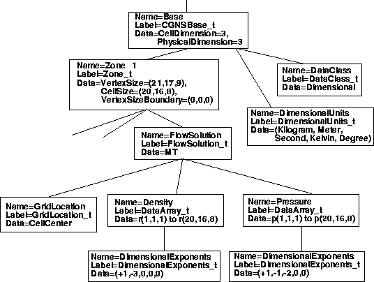
Notice in this example that a DataClass_t node and a DimensionalUnits_t node are placed near the top of the hierarchy, under CGNSBase_t. DataClass_t is specified as Dimensional, and DimensionalUnits_t are specified as (Kilogram, Meter, Second, Kelvin, Degree). These specify that, by and large, the entire database is dimensional with MKS units (anything that is not dimensional or not MKS units could be superseded at lower levels). Then, for each variable locally, one need only specify the DimensionalExponents, where one exponent is defined for each unit.
The layout of part of the resulting CGNS file from the above example is shown below. The density has units of kilogram/meter3, and the pressure has units of kilogram/(meter-second2). The grid coordinates (not shown in the figure) have units of meters.
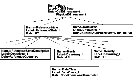
This example is for the relatively common occurrence of CFD data that is purely nondimensional, for which the reference state is arbitrary (unknown). This type is referred to as NormalizedByUnknownDimensional. Another nondimensional type, NormalizedByDimensional, for which the data is nondimensional but the reference state is specifically known, is not covered here.
For a NormalizedByUnknownDimensional database, the DataClass is recorded as such, but also a ReferenceState is necessary to define the nondimensionalizations used. (A ReferenceState_t node can be used for any dataset to indicate the global reference state (such as free stream), as well as quantities such as the reference Mach number and Reynolds number. A ReferenceState_t node was not included in the previous section, but it could have been.)
For the current example, we do not go into detail regarding the
choices of the items which should define the reference state for a
NormalizedByUnknownDimensional database.
We simply show in the example some typical choices which very often
would likely be included.
A detailed discussion of how the
data in ReferenceState_t defines the nondimensionalizations
is given in the SIDS document.
c   WRITE NONDIMENSIONAL INFO
       include 'cgnslib_f.h'
c   open CGNS file for modify
      call cg_open_f('grid.cgns',CG_MODE_MODIFY,index_file,ier)
      if (ier .ne. CG_OK) call cg_error_exit_f
c   we know there is only one base (real working code would check!)
      index_base=1
c   put DataClass under Base
      call cg_goto_f(index_file,index_base,ier,'end')
      call cg_dataclass_write_f(NormalizedByUnknownDimensional,ier)
c   put ReferenceState under Base
      call cg_state_write_f('ReferenceQuantities',ier)
c   Go to ReferenceState node, write Mach array and its dataclass
      call cg_goto_f(index_file,index_base,ier,'ReferenceState_t',1,
     +  'end')
      call cg_array_write_f('Mach',RealDouble,1,1,xmach,ier)
      call cg_goto_f(index_file,index_base,ier,'ReferenceState_t',1,
     +  'DataArray_t',1,'end')
      call cg_dataclass_write_f(NondimensionalParameter,ier)
c   Go to ReferenceState node, write Reynolds array and its dataclass
      call cg_goto_f(index_file,index_base,ier,'ReferenceState_t',1,
     +  'end')
      call cg_array_write_f('Reynolds',RealDouble,1,1,reue,ier)
      call cg_goto_f(index_file,index_base,ier,'ReferenceState_t',1,
     +  'DataArray_t',2,'end')
      call cg_dataclass_write_f(NondimensionalParameter,ier)
c   Go to ReferenceState node to write reference quantities:
      call cg_goto_f(index_file,index_base,ier,'ReferenceState_t',1,
     +  'end')
c   First, write reference quantities that make up Mach and Reynolds:
c   Mach_Velocity
      call cg_array_write_f('Mach_Velocity',RealDouble,1,1,xmv,ier)
c   Mach_VelocitySound
      call cg_array_write_f('Mach_VelocitySound',RealDouble,
     +   1,1,xmc,ier)
c   Reynolds_Velocity
      call cg_array_write_f('Reynolds_Velocity',RealDouble,
     +   1,1,rev,ier)
c   Reynolds_Length
      call cg_array_write_f('Reynolds_Length',RealDouble,
     +   1,1,rel,ier)
c   Reynolds_ViscosityKinematic
      call cg_array_write_f('Reynolds_ViscosityKinematic',RealDouble,
     +   1,1,renu,ier)
c
c   Next, write flow field reference quantities:
c   Density
      call cg_array_write_f('Density',RealDouble,1,1,rho0,ier)
c   Pressure
      call cg_array_write_f('Pressure',RealDouble,1,1,p0,ier)
c   VelocitySound
      call cg_array_write_f('VelocitySound',RealDouble,1,1,c0,ier)
c   ViscosityMolecular
      call cg_array_write_f('ViscosityMolecular',RealDouble,
     +   1,1,vm0,ier)
c   LengthReference
      call cg_array_write_f('LengthReference',RealDouble,
     +   1,1,xlength0,ier)
c   VelocityX
      call cg_array_write_f('VelocityX',RealDouble,1,1,vx,ier)
c   VelocityY
      call cg_array_write_f('VelocityY',RealDouble,1,1,vy,ier)
c   VelocityZ
      call cg_array_write_f('VelocityZ',RealDouble,1,1,vz,ier)
c   close CGNS file
      call cg_close_f(index_file,ier)
In this case, the only information added to the CGNS file is at the CGNSBase_t level. Note that Mach and Reynolds (which are stored under ReferenceState) are variables that are known as "NondimensionalParameter"s, so they must each contain a DataClass child node stating this (the local DataClass nodes supersede the overall NormalizedByUnknownDimensional data class that holds for everything else).
The layout of the relevant portion of the resulting CGNS file from the above example is shown below. Many of the reference quantities that appear under ReferenceState_t have been left out of the figure to conserve space.
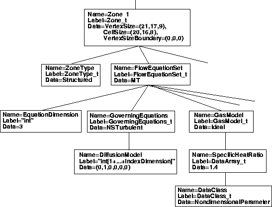
The FlowEquationSet_t node is useful for describing how a flow solution was generated. This is one of the useful self-descriptive aspects of CGNS that may improve the usefulness and longevity of a CFD dataset. For example, under this node, information such as the following may be recorded: the flow field was obtained by solving the thin-layer Navier-Stokes equations (with diffusion only in the j-coordinate direction); the Spalart-Allmaras turbulence model was employed, and an ideal gas assumption was made with γ = 1.4.
The following FORTRAN code segment writes some of
the above example flow equation set information
under the Zone_t node from our earlier
single-zone structured
grid example. (Note that
a FlowEquationSet_t node can also be placed at a higher level,
under the CGNSBase_t node. The
usual precedence rules apply).
c   WRITE FLOW EQUATION SET INFO
       include 'cgnslib_f.h'
c   open CGNS file for modify
      call cg_open_f('grid.cgns',CG_MODE_MODIFY,index_file,ier)
      if (ier .ne. CG_OK) call cg_error_exit_f
c   we know there is only one base (real working code would check!)
      index_base=1
c   we know there is only one zone (real working code would check!)
      index_zone=1
c   existing file must be 3D structured (real working code would check!)
c   Create 'FlowEquationSet' node under 'Zone_t'
      call cg_goto_f(index_file,index_base,ier,'Zone_t',index_zone,
     +   'end')
c   equation dimension = 3
      ieq_dim=3
      call cg_equationset_write_f(ieq_dim,ier)
c
c   Create 'GoverningEquations' node under 'FlowEquationSet'
      call cg_goto_f(index_file,index_base,ier,'Zone_t',index_zone,
     + 'FlowEquationSet_t',1,'end')
      call cg_governing_write_f(NSTurbulent,ier)
c   Create 'DiffusionModel' node under 'GoverningEquations'
      call cg_goto_f(index_file,index_base,ier,'Zone_t',index_zone,
     + 'FlowEquationSet_t',1,'GoverningEquations_t',1,'end')
      idata(1)=0
      idata(2)=1
      idata(3)=0
      idata(4)=0
      idata(5)=0
      idata(6)=0
      call cg_diffusion_write_f(idata,ier)
c
c   Create 'GasModel' under 'FlowEquationSet'
      call cg_goto_f(index_file,index_base,ier,'Zone_t',index_zone,
     + 'FlowEquationSet_t',1,'end')
      call cg_model_write_f('GasModel_t',Ideal,ier)
c   Create 'SpecificHeatRatio' under GasModel
      call cg_goto_f(index_file,index_base,ier,'Zone_t',index_zone,
     + 'FlowEquationSet_t',1,'GasModel_t',1,'end')
      call cg_array_write_f('SpecificHeatRatio',RealSingle,1,1,
     + gamma,ier)
c   Create 'DataClass' under 'SpecificHeatRatio'
      call cg_goto_f(index_file,index_base,ier,'Zone_t',index_zone,
     + 'FlowEquationSet_t',1,'GasModel_t',1,'DataArray_t',
     + 1,'end')
      call cg_dataclass_write_f(NondimensionalParameter,ier)
c   close CGNS file
      call cg_close_f(index_file,ier)
This particular example is specific to a 3-D structured zone. In an unstructured zone, the use of DiffusionModel is not valid. The layout of the relevant portion of the resulting CGNS file from the above example is shown below.
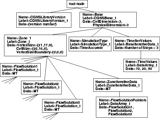
Time-dependent data (data with multiple flow solutions) can also be stored in a CGNS file. Different circumstances may produce data with multiple flow solutions; for example:
This section gives an example for type 1 only. Readers interested in the two other types should refer to the SIDS document. For a non-moving grid, the method for storing the multiple flow solutions is relatively simple: multiple FlowSolution_t nodes, each with a different name, are placed under each Zone_t node. However, there also needs to be a mechanism for associating each FlowSolution_t with a particular time and/or iteration. This is accomplished through the use of BaseIterativeData_t (under CGNSBase_t) and ZoneIterativeData_t (under each Zone_t). BaseIterativeData_t contains NumberOfSteps, the number of times and/or iterations stored, and their values. ZoneIterativeData_t contains FlowSolutionPointers as a character data array. FlowSolutionPointers is dimensioned to be of size NumberOfSteps, and contains the names of the FlowSolution_t nodes within the current zone that correspond with the respective times and/or iterations. Finally, a SimulationType_t node is placed under CGNSBase_t to designate what type of simulation (e.g., TimeAccurate, NonTimeAccurate) produced the data. (Note: the SimulationType_t node is not restricted for use with time-dependent data; any CGNS dataset can employ it!)
The following FORTRAN code segment writes some of the above
information, using our earlier single-zone
structured grid example.
For the purposes of this example, it is assumed that there are 3 flow
solutions from a time-accurate simulation, to be output as a function of
time to the CGNS file.
The variables r1 and p1 represent the density and
pressure at time 1, r2 and p2 are at time 2, and
r3 and p3 are at time 3.
c   WRITE FLOW SOLUTION TO EXISTING CGNS FILE
       include 'cgnslib_f.h'
c   open CGNS file for modify
       call cg_open_f('grid.cgns',CG_MODE_MODIFY,index_file,ier)
      if (ier .ne. CG_OK) call cg_error_exit_f
c   we know there is only one base (real working code would check!)
       index_base=1
c   we know there is only one zone (real working code would check!)
       index_zone=1
c   set up the times corresponding to the 3 solutions to be
c   stored:
       time(1)=10.
       time(2)=20.
       time(3)=50.
c   define 3 different solution names (user can give any names)
       solname(1) = 'FlowSolution1'
       solname(2) = 'FlowSolution2'
       solname(3) = 'FlowSolution3'
c   do loop for the 3 solutions:
       do n=1,3
c   create flow solution node
         call cg_sol_write_f(index_file,index_base,index_zone,solname(n),
     +     Vertex,index_flow,ier)
c   write flow solution (user must use SIDS-standard names here)
         if (n .eq. 1) then
           call cg_field_write_f(index_file,index_base,index_zone,index_flow,
     +       RealDouble,'Density',r1,index_field,ier)
           call cg_field_write_f(index_file,index_base,index_zone,index_flow,
     +       RealDouble,'Pressure',p1,index_field,ier)
         else if (n .eq. 2) then
           call cg_field_write_f(index_file,index_base,index_zone,index_flow,
     +       RealDouble,'Density',r2,index_field,ier)
           call cg_field_write_f(index_file,index_base,index_zone,index_flow,
     +       RealDouble,'Pressure',p2,index_field,ier)
         else
           call cg_field_write_f(index_file,index_base,index_zone,index_flow,
     +       RealDouble,'Density',r3,index_field,ier)
           call cg_field_write_f(index_file,index_base,index_zone,index_flow,
     +       RealDouble,'Pressure',p3,index_field,ier)
         end if
       enddo
c   create BaseIterativeData
       nsteps=3
       call cg_biter_write_f(index_file,index_base,'TimeIterValues',
     +   nsteps,ier)
c   go to BaseIterativeData level and write time values
       call cg_goto_f(index_file,index_base,ier,'BaseIterativeData_t',
     +   1,'end')
       call cg_array_write_f('TimeValues',RealDouble,1,3,time,ier)
c   create ZoneIterativeData
       call cg_ziter_write_f(index_file,index_base,index_zone,
     +   'ZoneIterativeData',ier)
c   go to ZoneIterativeData level and give info telling which
c   flow solution corresponds with which time (solname(1) corresponds
c   with time(1), solname(2) with time(2), and solname(3) with time(3))
       call cg_goto_f(index_file,index_base,ier,'Zone_t',
     +   index_zone,'ZoneIterativeData_t',1,'end')
       idata(1)=32
       idata(2)=3
       call cg_array_write_f('FlowSolutionPointers',Character,2,idata,
     +   solname,ier)
c   add SimulationType
       call cg_simulation_type_write_f(index_file,index_base,
     +   TimeAccurate,ier)
c   close CGNS file
       call cg_close_f(index_file,ier)
As cautioned for earlier coding snippets, dimensions must be set appropriately for all variables. The variable time (which is an array dimensioned size 3 in this case) contains the time values stored under BaseIterativeData_t. The layout of the resulting CGNS file from the above example is shown below. Compare this figure with the layout of a CGNS file for a simple Cartesian structured grid with a single flow solution. To conserve space, the GridCoordinates_t, ZoneType_t, and all nodes underneath FlowSolution_t have been left off.
A link associates one node to another within a CGNS tree, or even one node to another in a separate CGNS file altogether. This can be useful when there is repeated data; rather than write the same data multiple times, links can point to the data written only once.
One very important use of links that may be required by many users is to point to grid coordinates. This usage comes about in the following way. Suppose a user is planning to use a particular grid for multiple cases. There are several options for how to store the data. Among these are:
Item 1 is conceptually the most direct, and is certainly the recommended method in general (this is the way all example CGNS files have been portrayed so far in this document). However, if the grid is very large, then this method causes a lot of storage space to be unnecessarily used to store the same grid points multiple times. Item 2 may or may not be a viable option. If the user is striving to have the CGNS file be completely self-descriptive, with ReferenceState and FlowEquationSet describing the relevant conditions, then this method cannot be used if the ReferenceState or FlowEquationSet is different between the cases (for example, different Mach numbers, Reynolds numbers, or angles of attack). Item 3 removes this restriction. It uses links to the grid coordinates within the same file. Item 4 is similar to item 3, except that the grid coordinates and each flow solution are stored in separate files altogether.
A sample layout showing the relevant portions of two separate CGNS files for an example of item 4 is shown below. Note that for multiple-zone grids, each zone in FILE 1 in this example would have a separate link to the appropriate zone's grid coordinates in FILE 2.
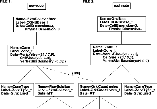
The CGNS API now has the capability to specify links and to query link information in a CGNS file. Previously this was only possible by use of the ADF core library software. However, when a CGNS file is open for writing and the link creation call is issued, the link information is merely recorded and the actual link creation is deferred until the file is written out upon closing it. Therefore, any attempt to go to a location in a linked file while the CGNS file is open for writing will fail. This problem does not exist when a CGNS file is open for modification as link creation is immediate.
Reading a linked CGNS file presents no difficulties for the API, because links are "transparent." As long as any separate linked files keep their name unchanged, and maintain the same position (within the Unix-directory) relative to the parent file, opening the parent file will automatically access the linked ones.