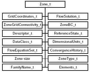
Fig. 1 Zone Data Structure
Diane M. A. Poirier
ICEM CFD Engineering, Berkeley, CA
Software Engineer, Member AIAA.
Robert H. Bush
United Technologies Research Center, East Hartford, CT
Group Leader, Simulation and Modeling, Associate Fellow AIAA.
Raymond R. Cosner
Boeing Phantom Works, St. Louis, MO
Senior Technical Fellow, Associate Fellow AIAA.
Christopher L. Rumsey
NASA Langley Research Center, Hampton, VA
Research Scientist, Associate Fellow AIAA.
Douglas R. McCarthy
Boeing Commercial Airplane Group, Seattle, WA
Principal Engineer, Member AIAA.
[This material is declared work of the U.S. Government and is not subject to copyright protection in the United States.]
The CFD General Notation System (CGNS) standard has grown significantly since its first public release in May 1998. The Standard Interface Data Structures (SIDS) and corresponding Application Programming Interface (API) have been extended to support unstructured analysis data and geometry-to-mesh association. Several other extensions are currently under review: rigid grid motion, deforming grid, timeaccurate and iterative data, chemistry, multigrid, rotating coordinate systems, periodic boundary conditions, wall functions, 2D axisymmetry and Cartesian data. In parallel with the growth of the CGNS standard, the CGNS governing body has evolved into an independent entity and established its own charter. Efforts have also been undertaken to promote CGNS as the ISO standard for the recording of aerodynamic data. This paper reviews the progress made by CGNS over the past eighteen months. It first describes the technical advances in the CGNS database standard, followed by an overview of the new CGNS organization. Then the status of the CGNS in the ISO standardization process is presented, as well as a review of implementation and dissemination of CGNS.
The CGNS (CFD General Notation System) project originated during 1994 through a series of meetings that addressed improved transfer of NASA technology to industry. A principal impediment in this process was the disparity in I/O formats employed by various flow codes, grid generators, and other utilities, and CGNS was conceived as a means to promote "plug-and-play" CFD. Agreement was reached to develop CGNS at Boeing, under NASA Contract NAS1-20267, with active participation by a team of CFD researchers from NASA's Langley, Lewis (now Glenn), and Ames Research Centers, McDonnell Douglas Corporation (now part of Boeing), and Boeing Commercial Airplane Group. This team, which was joined by ICEM CFD Engineering Corporation of Berkeley, California in 1997, undertook the core of the development. However, in the spirit of creating a completely open and broadly accepted standard, all interested parties were encouraged to participate; the US Air Force and Arnold Engineering Development Center were notably present. From the beginning, the purpose was to develop a system that could be distributed freely, including all documentation, software and source code. This goal has now been fully realized; further, as described below, control of CGNS has been completely transferred to a public forum known as the CGNS Steering Committee.
The specific purpose of CGNS was to provide a standard for recording and recovering computer data associated with the numerical solution of the equations of fluid dynamics. The intent was to facilitate the exchange of CFD data between sites, between applications codes, and across computing platforms, and to stabilize the archiving of CFD data. The format implemented by this standard was to be (1) general, (2) portable, (3) expandable, and (4) durable.
The resulting system today consists of a collection of conventions, and software implementing those conventions, for the storage and retrieval of CFD data. The system consists of two parts: (1) a standard format for recording the data, and (2) software that reads, writes, and modifies data in that format. The format is a conceptual entity established by the documentation; the software is a physical product supplied to enable developers to access and produce data recorded in that format.
The principal target is the data normally associated with compressible viscous flow (i.e., the Navier-Stokes equations), but the standard is also applicable to subclasses such as Euler and potential flows, and superclasses such as chemically reacting flows. The initial release addressed multi-block grids, flow fields, boundary conditions, and block-to-block connection information, as well as a number of auxiliary items, such as non-dimensionalization, reference states, and equation set specifications. This stage of development was summarized in reference 6. The current paper describes the extensions undertaken since, including unstructured mesh, moving grids, connections to geometry definition, and chemistry.
It is worth noting that extensibility is a fundamental design characteristic of the system, which in principal could be used for other disciplines of computational field physics, such as acoustics or electromagnetics, given the willingness of the cognizant scientific community to define the conventions.
The standard format, or paper convention, part of CGNS consists of two fundamental pieces. The first, known as the Standard Interface Data Structures (SIDS) (Ref. 2), describes in detail the intellectual content of the information to be stored. It defines, for example, the precise meaning of a "boundary condition". The second, known as the File Mapping (Ref. 4), defines the exact location in a CGNS file where the data is to be stored.
The implementation, or software, part of CGNS likewise consists of two separate entities. CGNS files are read and written by a stand-alone database manager called ADF (Advanced Data Format) (Ref. 3). ADF manages a tree-like data structure, implemented as a binary file. Since the format of this file is completely controlled by ADF, and since ADF is written in ANSI C (FORTRAN wrappers are provided), these files and ADF itself are portable to any environment which supports ANSI C. ADF is available separately and constitutes a useful tool for the storage of large quantities of scientific data.
ADF, however, implements no knowledge of CFD or of the File Mapping. To simplify access to CGNS files, a second layer of software known as the Mid-Level Library (Ref. 5) is provided. This layer is in effect an API, or Application Programming Interface for CFD. The API incorporates knowledge of the CFD data structures, their meaning and their location in the file, enabling applications such as flow codes and grid generators to access the data in familiar terms. The API is therefore the piece of the CGNS system most visible to applications developers. Like ADF, the API is written in ANSI C; all public API routines have FORTRAN counterparts.
The overall architecture of CGNS is that of shared files accessible by the various software tools common to CFD: solvers, grid generators, field visualizers, and postprocessors. These applications must be modified, using the API, to be able to access CGNS data. Each application then serves as an editor of the data, adding to, modifying or interpreting it according to that application's specific role. The user, or a locally developed user interface, remains responsible for executing the required actions and for the disposition of the files.
The CGNS elements are documented individually. Visitors to the main web site, www.CGNS.org, will find all documentation, as well as the software, both compiled and source code. For those new to CGNS, the Overview (Ref. 1) and the CGNS System paper (Ref. 6) are recommended.
The first release of the CGNS standard supported structured topology, where multi-block connectivity could be either one-to-one abutting, mismatched abutting or overset. It defined standards for the storage of grid coordinates, flow solutions, boundary conditions, convergence history, and reference state. Dimensional units and non-dimensionalization information could be associated with each type of data. Additionally, it provided conventions for archiving the governing equations including the gas, viscosity, thermal conductivity, turbulence and diffusion models. It also provided for the recording of descriptive data throughout the file.
Following this first release, the project to add support for unstructured topology and geometry-to-mesh association was immediately undertaken. Proposals were collected and the CGNS team organized meetings with CFD researchers familiar with unstructured topology and/or geometry data. New data structures were defined and added to the standard to hold the additional information, and the CGNS library was augmented to support the new data structures. Paragraphs 2.1 and 2.2 describe the implementation of the unstructured topology and geometry-to-mesh association in the CGNS standard.
Several other extensions are currently under work at various stages of maturity. The proposals for adding support for rigid grid motion, point by point grid motion (deforming grid), and iterative or time-accurate data are pending final approval and will be the next addition to the CGNS API. These new data structures are described in paragraphs 2.3, 2.4, and 2.5. Other proposals still at the discussion level include the addition of chemistry, multigrid, rotating coordinates, periodic boundary conditions, wall functions, 2D axisymmetry and Cartesian data.
This section describes how the addition of unstructured data was incorporated to the CGNS system, and how it affected the Standard Interface Data Structures (SIDS).
There are basically two major differences between the way structured and unstructured mesh data are recorded. In a structured mesh, a node is identified with its computational coordinates. A node has as many computational coordinates as there are dimensions in the mesh. For example, in a 3D grid, any node position in the mesh is uniquely defined giving three computational coordinates. The physical coordinate vectors and all the field vectors (solution, discrete boundary conditions, etc.) use the computational coordinates of each node as array indices. However, the mapping of the physical coordinates to the computational coordinates is only possible in a structured grid. In an unstructured grid, the nodes are simply given a number from 1 to N, where N is the number of nodes.
The second major difference in the way structured and unstructured grids are recorded is the element definition. In a structured grid, the elements can always be recomputed easily using the computational coordinates, and therefore they are usually not written in the data file. For an unstructured grid, the element connectivity can not be easily built, so this additional information is generally added to the data file. The element information typically includes the element type or shape, and the list of nodes for each element.
In order to conciliate the differences between structured and unstructured mesh files, two new parameters were introduced. The SIDS already defined the expression IndexDimension as the number of computational coordinates required to uniquely define a node in a mesh. For structured grids, this number equals the dimension of the mesh cells. For unstructured grid, only one index is necessary to locate a node in the mesh, regardless of the dimension of the mesh cells. The parameter IndexDimension is no longer sufficient to indicate the dimensionality of the cells. Therefore a second dimensional parameter called CellDimension was defined. For structured meshes, CellDimension and IndexDimension are always equal, but for unstructured grids, they differ when the cells have two or more dimensions.
To define a vector in a mesh, such as the normal vector to a mesh face, one needs to know the number of dimensions in the physical space. For example, the surface mesh around an aircraft is composed of bi-dimensional cells (faces or shell elements), but expressing the normal vectors to these cells requires three-dimensional physical coordinates. This leads to the definition of a third dimensional parameter, the PhysicalDimension. In addition to the topolgy type (structured or unstructured), these three parameters, IndexDimension, CellDimension and PhysicalDimension, are necessary to uniquely define a particular mesh type. For example, an unstructured surface mesh on an aircraft implies that:
   IndexDimension=1
   CellDimension=2
   PhysicalDimension=3
Table 1 summarizes all possible combinations of these parameters for structured and unstructured grids.
| Mesh type | IndexD | CellD | PhysD | |||
|---|---|---|---|---|---|---|
| 3D structured | 3 | 3 | 3 | |||
| 2D structured in 2D space | 2 | 2 | 2 | |||
| 2D structured in 3D space | 2 | 2 | 3 | |||
| 1D structured in 1D space | 1 | 1 | 1 | |||
| 1D structured in 2D space | 1 | 1 | 2 | |||
| 1D structured in 3D space | 1 | 1 | 3 | |||
| 3D unstructured | 1 | 3 | 3 | |||
| 2D unstruct. in 2D space | 1 | 2 | 2 | |||
| 2D unstruct. in 3D space | 1 | 2 | 3 | |||
| 1D unstruct. in 1D space | 1 | 1 | 1 | |||
| 1D unstruct. in 2D space | 1 | 1 | 2 | |||
| 1D unstruct. in 3D space | 1 | 1 | 3 | |||
The definition of the new dimensional parameters CellDimension and PhysicalDimension allowed using most of the existing SIDS with minimal changes when adding support for unstructured grids. By selecting the appropriate dimensional parameter to set the size of data arrays, the same data structures can be used for both structured and unstructured cases. For example, the number of nodes can be recorded in the array:
Nnodes[IndexDimension]
For a 3D-structured grid, this automatically leads to a 3D array containing the number of nodes in each of the three computational directions. On the other hand, it results in a mono-dimensional array for a 3D-unstructured grid. The solution vector and grid coordinates are also recorded in arrays of IndexDimension dimensions. Therefore, their definition is independent of the mesh type as well. The new parameters CellDimension and PhysicalDimension also fulfill the purpose of generalizing the data structures for both topology types. The connectivity between zones is defined using interpolation coefficients to locate each point of a zone in the neighboring zone. The number of coefficients required is equal to CellDimension, independently of the mesh type. Similarly, position vectors or normal vectors are defined using the dimensional parameter PhysicalDimension in both types of meshes.
As a result, the unstructured zones were introduced into the CGNS system without the need to define a new data structure specific to unstructured mesh. Not only does this simplify the SIDS, but it also facilitates the API and its implementation. As before, a CGNSBase_t data structure may contain one to several zones. The only difference now is that some of these zones may be structured, while others are unstructured.
To accommodate the definition of unstructured zones, two new children
were added to the Zone_t data structure, as shown in Figure 1.
The node ZoneType_t records if the zone is structured
or unstructured. It simply holds the data-name identifier
Structured or Unstructured. The other new child is the
data structure Elements_t that holds the element information
for unstructured grids. A zone may contain several Elements_t
data structures. Each Elements_t data structure holds several
child nodes, as illustrated in Figure 2.
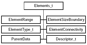
The ElementRange node contains the index of the first and last elements defined in the ElementConnectivity_t array. The elements are indexed with a global numbering system for all element sections in the same Zone_t data structure. They are also listed as a continuous list of element numbers within a single element section. These element indices may be used elsewhere in the database to define a boundary condition patch, or to specify zone to zone connectivity. ElementType_t is an enumeration of the supported element types.
   ElementType_t := enumeration(
      Null, NODE, BAR_2, BAR_3,
      TRI_3, TRI_6, QUAD_4, QUAD_8, QUAD_9,
      TETRA_4, TETRA_10, PYRA_5, PYRA_14,
      PENTA_6, PENTA_15, PENTA_18,
      HEXA_8, HEXA_20, HEXA_27, NGON_n);
where NGON_n is used to express a polygon of n nodes.
ElementSizeBoundary indicates if the elements are sorted, and how many boundary elements are recorded. By default, ElementSizeBoundary is set to zero, indicating that the elements are not sorted. If the elements are sorted, ElementSizeBoundary is set to the number of elements at the boundary, and the boundary elements are listed first in the ElementConnectivity array.
For face elements in 3D, or bar elements in 2D, information regarding the parent cells may be recorded. ParentData holds the parent cell numbers of a face element, and the face position within these parent elements. At the boundaries, the second parent is set to zero.
Another important segment of the CFD data is the description of the geometry data. The definition of the underlying geometry is mandatory to perform operations such as mesh refinement or coarsening. It may also be necessary in various post-processors for the analysis and display of the results. This section describes how the geometry-to-mesh association was incorporated in the CGNS system.
The goal in the CGNS geometry specification is to connect the geometry definition of the various components of a model to the computational grid. It enables the recovery of the geometry corresponding to a given mesh surface, or vice versa.
The CGNS team decided not to create a new geometry file format, but rather to link to the existing ones. This approach offers several advantages with respect to incorporating the CGNS system into existent software applications. Most CFD users have already adopted a CAD system file format, which is most likely intricately connected to their software. Agreeing to change to a new CAD file format could imply major rewriting of several CFD software tools. At the very least, translators would be needed to interface back and forth between each CAD file format and a new CGNS standard. This would make the implementation of the new standard more laborious.
In addition, most existing CAD file formats have proven to be effective and sufficient to accurately define the geometry data and to facilitate data exchange between sites and applications. To create a new format would duplicate existing work. For these reasons, it was decided that the CAD geometric entities described in the CAD database would not be redefined within the CGNS file. Instead the CGNS system would incorporate the geometry-to-grid connectivity by referring directly to the geometric entities defined in these CAD files.
Since there is rarely a 1-to-1 connection between mesh regions and geometric entities, the geometry-to-mesh associations are set through one layer of indirection. Rather than mapping the geometry data directly to the mesh entities, the association is made indirectly using a layer of objects called CFD families. A CFD family may be composed of one or several mesh regions (blocks or boundary condition patches). In the corresponding CAD file, the same family is represented by a group of geometric entities such as b-spline curves and surfaces, on which the mesh faces are projected. Each family is contained solely within a single CAD database.
The association between a node and a CFD family is easily made invariable under most CAD modeling operations. The association between a node and a specific CAD entity can not. Therefore one of the main advantages of this layer of indirection concept is that the mesh density and geometric entities may be modified without altering the association between nodes and families, or between families and geometric entities. This is very beneficial when handling boundary conditions and properties. Instead of setting boundary conditions directly on mesh entities, they can be associated with the families (FamilyBC_t). Since the families are stable in the sense that they are not subject to operations such as geometric changes, modification of mesh topology, mesh refinement or coarsening, the boundary conditions do not need to be redefined each time the model is modified.
For the purpose of defining properties, families are also supported on groups of interior mesh elements. For example, a 3D mesh may comprise several CFD families of 3D elements, and several CFD families of boundary elements. The families of 3D elements are typically used to specify volume properties, e.g. material properties such as porosity, while those containing 2D elements serve primarily to define boundary conditions.
The implementation of the geometry-to-mesh association implied a few
additions to the SIDS. The most important one was to create a new data
structure to hold the CFD family data. The new data structure is called
Family_t and is added to the CGNSBase_t structure for
each CFD family of the model. Figure 3 shows the layout of this data
structure within the CGNS hierarchical database.
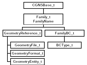
The Family_t data structure contains the name of the file where the geometry is stored (GeometryFile_t), as well as the geometry format (GeometryFormat_t) in which the file is written (IGES, SDRC, Unigraphics, Pro-Engineer, etc.). In addition, one may specify for each CFD family, the name of the geometry entities (GeometryEntity_t) to be associated with the family. There may be one to several geometry entities for a given family. If no geometry entity is specified, it is assumed by default that the family name and the geometry entity name are the same.
Node and family association is implemented by assigning a FamilyName to a group of nodes of the computational grid. The family name consists of an alphanumeric string. A FamilyName is an optional attribute to each zone and boundary condition patch. It is stored within the CGNS file under the zone (Zone_t) or the boundary condition (BC_t) data structures.
The following three sections describes proposals for the addition of rigid grid motion, arbitrary grid motion and iterative or time-accurate data. These proposals are mature and should be soon incorporated to the API.
The addition of rigid body motion data to the CGNS file enables the use of moving grids such as might be required for turbo-machinery applications. The mesh location is determined without the need to alter the original mesh definition recorded under GridCoordinates_t. A new data structure named RigidGridMotion_t is created to record the necessary data defining a rigid translation and/or rotation of the grid coordinates.
It is proposed that the rigid grid motion be recorded independently for each zone of the CGNS base. Therefore the RigidGridMotion_t data structure would be added under each zone data structure (Zone_t). There may be zero to several RigidGridMotion_t nodes under a Zone_t node. The multiple rigid grid motion definitions may be associated with different iterations or time steps in the computation. This association is recorded under the IterativeOrTemporalData_t data structure (paragraph 2.5).
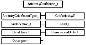
The RigidGridMotion_t data structure is illustrated in Figure 4.
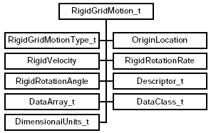
RigidGridMotionType_t is an enumeration type that describes the type of rigid grid motion. It may be set to either ConstantRate or VariableRate. ConstantRate is used when the RigidVelocity and RigidRotationRate are both constant and at least one is nonzero. OriginLocation holds the physical coordinates of the origin before and after the rigid grid motion. The RigidRotationAngle node records the rotation angles about each axis of the translated coordinate system. RigidVelocity is the velocity vector of the origin translation and RigidRotationRate is the rotation rate vector about the axis of the translated coordinate system.
Additional optional elements are DataClass_t, DimensionalUnits_t and Descriptor_t. Any number of DataArray_t nodes may also be recorded under the RigidGridMotion_t data structure to support data not covered by this specification.
The ArbitraryGridMotion_t data structure allows the CGNS file to contain information about arbitrary grid deformations such as might be required for unsteady aeroelastic applications. If not present, the grid is assumed to be rigid.
It is proposed that the arbitrary grid motion be recorded independently for each zone of the CGNS base. Therefore the ArbitraryGridMotion_t data structure would be added under each zone data structure (Zone_t). There may be zero to several ArbitraryGridMotion_t nodes under a Zone_t node. The multiple arbitrary grid motion definition may be associated with different iterations or time steps in the computation. This association is recorded under the IterativeOrTemporalData_t data structure (paragraph 2.5).
The ArbitraryGridMotion_t data structure is illustrated in
Figure 5.
The DataArray_t nodes are used to store the components of the grid velocity vector. Table 2 lists the new data-name identifiers proposed to record these vectors in the Cartesian, cylindrical, spherical, and auxiliary coordinate systems.
| Data-Name Identifier | Nodes Velocity | Units | ||
|---|---|---|---|---|
| GridVelocityX | x-component | L/T | ||
| GridVelocityY | y-component | L/T | ||
| GridVelocityZ | z-component | L/T | ||
| GridVelocityR | R-component | L/T | ||
| GridVelocityTheta | Theta-component | α/T | ||
| GridVelocityPhi | Phi-component | α/T | ||
| GridVelocityXi | Xi-component | L/T | ||
| GridVelocityEta | Eta-component | L/T | ||
| GridVelocityZeta | Zeta-component | L/T | ||
ArbitraryGridMotionType_t is an enumeration type that describes the type of arbitrary grid motion. The type is either NonDeformingGrid or DeformingGrid. The only required element of the ArbitraryGridMotion_t data structure is the ArbitraryGridMotionType. Thus, even if a deforming grid application does not require the storage of grid velocity data, the ArbitraryGridMotion_t node must exist, with ArbitraryGridMotionType set to DeformingGrid, to indicate that the mesh coordinates after deformation are recorded under the given zone.
The DataClass_t, DimensionalUnits_t and Descriptor_t nodes may optionally be specified under the RigidGridMotion_t nodes. Rind is an optional field that indicates the number of rind planes included in the grid velocity data. It only applies to structured zones. The GridLocation specifies the location of the velocity data with respect to the grid; if absent, the data is assumed to coincide with grid vertices (i.e. GridLocation = Vertex).
In addition to the creation of the ArbitraryGridMotion_t data structure to record the velocity of each grid point, it is proposed to allow multiple GridCoordinates_t nodes under a Zone_t. This enables the storage of the instantaneous grid locations at different time steps or iterations. The original grid coordinates definition, as currently defined in the SIDS, remains unchanged with the name GridCoordinates. Point by point grid velocity implies a deformation (or potentially only motion) of the grid points relative to each other. Because the original grid coordinates definition is to remain unchanged, any deformed coordinates are to be written with a different name (e.g., GridCoordinates1 or another user-defined name) and are to be pointed to using the GridCoordinatesPointers in the data structure IterativeOrTemporalData_t (paragraph 2.5).
In order to keep a record of time dependent or iterative solutions and mesh data, a new data structure called IterativeOrTemporalData_t is defined. This new data structure contains information relative to each time step or iteration stored.
It is proposed that the interative and time-accurate _data structure be recorded independently for each zone of the CGNS base. Therefore it would be added under each zone data structure (Zone_t). There may be zero to several IterativeOrTemporalData_t nodes under a Zone_t node.
Several different simulation types may be recorded under CGNS, but all zones under the same CGNS base must have the same simulation type. It is proposed to add a new Descriptor_t node under the CGNSBase_t data structure to specify which simulation type is recorded in the base. The Descriptor_t node named SimulationType holds a simulation type identifier such as NonTimeAccurate or TimeAccurate.
The IterativeOrTemporalData_t data structure is illustrated in
Figure 6.
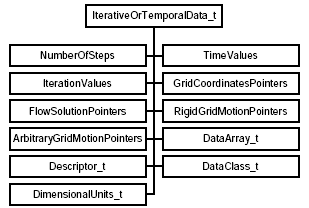
The number of time steps or the number of iterations is a required element of this data structure, and is recorded in the field NumberOfSteps. TimeValues or IterationValues must also be defined. If both are used, there must be a one-to-one correspondence between them. The data arrays RigidGridMotionPointers, GridCoordinatesPointers, FlowSolutionsPointers and ArbitraryGridMotionPointers are optional. Their purpose is to associate with each time step or iteration the appropriate data structures for rigid grid motion, arbitrary grid motion, grid coordinates and flow solutions. They refer by name to data structures within the current zone. The name "Null" is used when a particular time or iteration does not have a corresponding data structure to point to.
The DataClass_t, DimensionalUnits_t and Descriptor_t nodes may optionally be specified under the IterativeOrTemporalData_t nodes. In addition, any number of DataArray_t node is allowed. These should be used to record data not covered by this specification.
The data structures defining rigid grid motion, arbitrary grid motion and iterative or time-accurate data are the first proposals to follow the extension review process recently established by the CGNS Steering Committee. The following section describes the new organization governing CGNS, and how CGNS users may submit proposals for extensions to the existing standard.
The CGNS Steering Committee has been formed to ensure the continuation of the CFD General Notation System. The Committee has adopted a Charter that was approved by the Committee on 21 October 1999. The Charter lays out the mission, organization and governing principles of the Steering Committee. The Charter can be found at the CGNS web site, at www.CGNS.org. In summary, the Charter defines several responsibilities of the CGNS Steering Committee that support its fundamental mission. They include:
The CGNS Steering Committee is organized as a voluntary organization that governs by consensus. The Committee meets at a minimum of once per year, and is represented by a Chairperson. The Chairperson coordinates activities, facilitate meetings and serves as a focal point for the Committee. The Charter explicitly states that all parties are welcome to bring forward issues and participate in the development of the Standard, whether or not they are members of the Steering Committee. The CGNS Steering Committee is made up of representatives from specific institutions, rather than individuals. Membership on the Committee is currently limited to 15 institutions that participate in the development, maintenance, distribution and use of the Standard. The initial members of the Steering Committee are:
The CGNS Charter also defines Standing Committees to which the Steering Committee may delegate responsibilities. These committees make recommendations to the Steering Committee, which retains the authority to make final decisions. The current Standing Committees are:
The Software Focal Point is the prime source for maintaining and distributing the existing documentation and software, and developing and distributing new software resulting from extensions to the standard.
The CGNS Charter also lays out the governing principles that are to be followed. In general, the Charter calls on the Committee to adhere to the philosophy used for "free software", as defined under the GNU Lesser Public License. In particular, the freedom to:
These freedoms promote the promulgation of the CGNS Standard by allowing users the freedom to redistribute copies, with or without modifications, either gratis or charging a fee for distribution, to anyone anywhere.
The Charter also calls for changes and additions to the Standard. CGNS has been developed with the key concepts of flexibility and extensibility in mind. In order to address a perceived need or deficiency in the Standard, a proposal must be submitted to the Steering Committee. The proposal is then presented in an open and public forum, and includes a draft of changes to the SIDS and File Mappings. Finally, the Steering Committee is responsible for accepting, altering or rejecting the proposal, and determines the timetable for implementation. The primary requirement for any proposal is to maintain code compatibility with the existing Standard.
The Boeing Company has been a participant from the start in the development of the CGNS standard for CFD data. For many years, Boeing also has taken an active role in the development of ISO standards for the exchange of engineering data. In February 1998, Boeing initiated an activity to establish an evolved form of the CGNS data standard as an ISO standard for archiving and exchanging aerodynamic data. Boeing's plan to lead the development of this standard was presented to ISO Technical Committee 184 (Industrial Automation Systems and Integration), Subcommittee 4 (Industrial Data), Working Group 3 (Product Modeling) during their meeting in January 1999.
In November 1999, Boeing presented to this Working Group a formal proposal for development of an aerodynamics data exchange standard. This proposal has been accepted by the ISO organization. The effort to develop an Aerodynamics Application Protocol (AP) is now formally sanctioned as an ongoing ISO project. The end product will be an ISO/STEP AP2xx (200-series number not yet assigned).
The cognizant ISO subcommittee (SC4 - Industrial Data) consists of seventeen voting member countries. Decisions throughout this process are made on the basis of one country, one vote. The seven stages in developing an ISO Application Protocol (AP) standard (Ref. 7) are:
The ISO approval process specifies a schedule for advancing through these stages. Most ISO standards projects begin with an idea and a clean sheet of paper. CGNS, however, is at a far more advanced state. Therefore, it is believed that this initiative can advance through the approval stages at an accelerated pace. The ISO approval "clock" begins running when the New Work Item is approved. Current plans anticipate this approval in October 2000. Table 3 display the ISO required schedule and planned completion dates, based on this assumed approval date.
The current plan is to focus first on completion of the CFD data standard based on CGNS. However, the ultimate scope also will encompass other forms of aerodynamic and fluid dynamic digital data, including wind tunnel data and flight test data. Once the CFD portion of the AP standard is in place, we anticipate extending the AP by amendments to include these additional types of data. The schedule presented above applies to the initial standards process, not to the process of planned amendments.
| Milestone | ISO Required Completion Date | Planned Completion Date | ||
|---|---|---|---|---|
| New Work Item (NWI) | Oct 2000 | Oct 2000 | ||
| Working Draft | Apr 2001 (6 mo. from NWI) | Oct 2000 | ||
| Committee Draft | Oct 2002 (2 yr. from NWI) | Apr 2001 ? | ||
| Final Draft International Standard | Oct 2003 (3 yr. from NWI) | 2002 ? | ||
Based on initial feedback from ISO subcommittee members, the scope also should extend beyond aerospace aerodynamics to include ground vehicle fluid dynamics and ship hydrodynamics. In a planning meeting held in December 1999, a decision was taken to accept this requested increase in scope. Accordingly, the project has been re-titled from "Aerodynamics AP" to "Fluid Dynamics AP". However, the planning sequence is unchanged: to establish a CFD data exchange standard first (in accord with the schedule presented above), and to extend the data exchange standard subsequently to accommodate other types of digital data in fluid dynamics.
In the process of reaching agreement on an ISO standard, it is anticipated that significant modifications may be proposed based on the current CGNS standard. People or organizations wishing to participate in this process are invited to contact the CGNS Steering Committee, or the third author of this paper (Cosner) via e-mail at raymond.r.cosner@boeing.com.
CGNS has been welcome by the CFD community worldwide. The effort of standardizing the data exchange format for aerodynamic data is considered by most a necessity long overdue. Since its first release in May 1998, the CFD General Notation System has received an overwhelming support from Academia, Industry, and Research Agencies. At the time of writing, 240 users from over 25 countries have registered at the CGNS web site. In addition to implementing the CGNS standard into their own applications, several users participate actively in new extensions to the CGNS system.
The CGNS Steering Committee is aware of several CFD applications, from both research and commercial organizations in U.S.A. and Europe, having implemented or interfaced with the CGNS standard successfully:
Figure 7 illustrates an example of a typical CGNS file. It is given to provide the reader with an idea of the type of information that goes into a CGNS file and how it is organized. This particular example is from the structured-grid CFL3D code. It is for a one-zone grid (to keep the example relatively short), and does not include grid connectivity information, which would be necessary for multiple zone grids or a single zone grid that connected with itself. Each ADF node is represented with its name and label (name/label). However, when the only difference between the name and label is "_t", the name has been omitted.
   ROOT node
   + CGNSLibraryVersion_t
   + Base/CGNSBase_t
     + Zone1/Zone_t
       + ZoneType_t
       + GridCoordinates_t
         + CoordinateX/DataArray_t
         + CoordinateY/DataArray_t
         + CoordinateZ/DataArray_t
       + ZoneBC_t
         + Ilo_Seg1/BC_t
           + PointRange/IndexRange_t
           + CFL3Dtype/Descriptor_t
         + ...(other boundary conditions...)
       + FlowSolution_t
         + GridLocation_t
         + Rind_t
         + Density/DataArray_t
         + VelocityX/DataArray_t
         + ...(other solution arrays)
       + FlowEquationSet_t
         + EquationDimension/"int"
         + GoverningEquations_t
         + DiffusionModel/"int[1+...+IndexDimension]"
         + GasModel_t
         + ViscosityModel_t
         + ThermalConductivityModel_t
         + TurbulenceClosure_t
         + TurbulenceModel_t
     + GlobalConvergenceHistory/ConvergenceHistory_t
       + RSDMassRMS/DataArray_t
       + CoefLift/DataArray_t
       + ...(other convergence parameters)
     + DataClass_t
     + ReferenceState_t
       + Mach/DataArray_t
       + Reynolds/DataArray_t
       + VelocitySound/DataArray_t
       + ViscosityKinematic/DataArray_t
       + Density/DataArray_t
       + Length/DataArray_t
       + ...(other reference parameters)
Fig. 7 Example of Implementation
The CGNS system was designed to provide a complete description of CFD data, so that others could unambiguously read and use it. This example is a 3-D case in which volume data is recorded. The parameters CellDimension and PhysicalDimension are stored in the CGNSBase_t node, while IndexDimension is recorded for each zone. The Zone_t node contains information about the zone's grid size, for example, (2 × 65 × 97) vertices and (1 × 64 × 96) cells. ZoneType_t in this example specifies Structured, and the grid coordinates are written under GridCoordinates_t.
The boundary conditions are specified under ZoneBC_t. For example, the data for the boundary patch "Ilo_Seg1" might be BCSymmetryPlane. IndexRange_t gives the index range over which this boundary condition applies. Note that in this example, the user has also added the descriptor node under ZoneBC_t called CFL3DType. This node is not part of the CGNS standard, but rather was added for convenience in order to tie in the CGNS boundary condition identifier with a type specific to the CFL3D code. Descriptors like this may be sprinkled throughout the CGNS file. They provide an easy way to add descriptive comments to a file for the benefit of present or future readability. Their existence in no way limits the ability of others to read and use the file.
Flow solution information is stored in data arrays under the FlowSolution_t data structure. CFL3D gives this information at cell centers; thus, GridLocation_t specifies CellCenter in the example. The node Rind_t indicates the number of rind cells (ghost cells) at which flow solution information is also given. For example, if there is one rind cell specified at jlo and one at jhi, then the expected dimensions of the data arrays in this example would be (i × j × k) = (1 × 64 + 2 × 96).
The FlowEquationSet_t node contains information about how the solution was run. In the example presented here, EquationDimension is 3, GoverningEquations is NSTurbulent, GasModel is Ideal, ViscosityModel is SutherlandLaw, ThermalConductivityModel is ConstantPrandtl, TurbulenceClosure is EddyViscosity, and TurbulenceModel is OneEquation_SpalartAllmaras. The node DiffusionModel indicates whether thin-layer or full Navier-Stokes was used, and in which index directions.
The convergence history may be stored for each individual zone or globally under the CGNSBase_t node, as shown in this example. DataClass_t specifies the type of data given. The class of data used by the CFL3D code is NormalizedByUnknownDimensional. Then, further information regarding the reference quantities is given under ReferenceState_t. The nodes VelocitySound, ViscosityKinematic, Density and Length give the reference levels by which all quantities in the file have been nondimensionalized. Other nodes such as Prandtl, Temperature, and SpecificHeatRatio also appear in the file but have been left off in the example for the sake of brevity.
This paper described the advances in the CGNS database standard for aerodynamics and CFD. Since 1994, CGNS has grown into a data standard sufficient to support the majority of CFD applications while providing for easy data exchange between sites, computing environments and applications. Since the initial public release of the CGNS documentation and software in May 1998, additions to the standard included the incorporation of unstructured topology and mesh-to-geometry association.
In parallel to the growth of the standard, the CGNS organization has been transformed into an open and public committee whose main purposes is to ensure the continuation of CGNS. The CGNS Steering committee has adopted in 1999 a Charter defining its governing rules and mission. In addition to the maintenance of the current standard, the CGNS Steering Committee has the responsibility to allow for the growth of the standard. To that effect, proposals for modifications and extensions of the standard may be submitted by anyone. Three new proposals for rigid and arbitrary grid motions, as well as time-accurate data, have been reviewed and developed according to the extension process defined in the new adopted Charter. These proposals are at their last stage of approval before being officially incorporated to the CGNS standard.
The CGNS standard is also the object of an ISO standardization effort for Fluid Dynamics data. This project, initiated by the Boeing Company, has been accepted by the ISO organization and is now advancing to the third stage of the ISO approval process.