Armin Wulf
ICEM CFD Engineering
January 13 1999
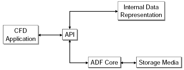
The ADF Core is composed of 34 low level functions performing the following operations:
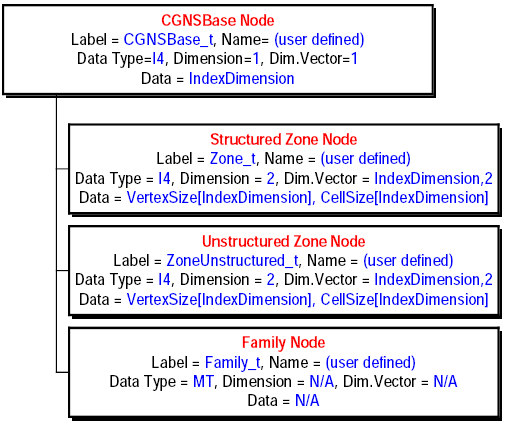
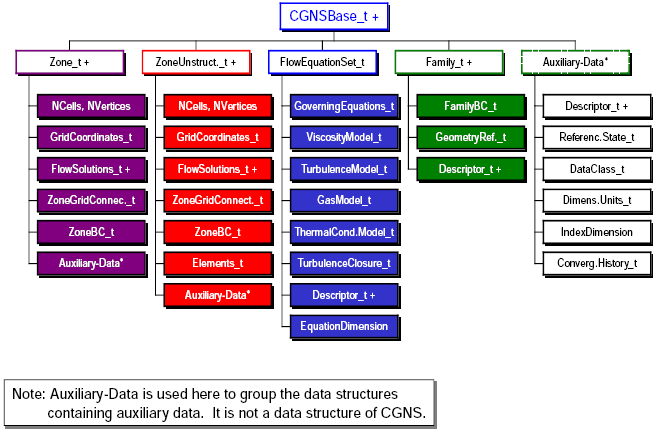
   CGNSBase_t: = {
   int IndexDimension;
   List (Zone_tZone1,...ZoneN);
   ...}

   Zone_t : = {
      int[IndexDimension] VertexSize, CellSize;
      ...}
For CGNSBase_t,
For Zone_t,
   int cg_nbases(int FileNo, int *nbases);

   int cg_base_read(int FileNo, int BaseNo, char *BaseName, int *IndexDimension);

   int cg_nzones(int FileNo, int BaseNo, int *nzones);

   int cg_zone_read(int FileNo, int BaseNo, int ZoneNo, char *ZoneName, int *ZoneSize);
   int cg_open(char *filename, int mode, int *fn);
   int cg_close(int fn);
   cg_open(filename, MODE_READ, &fn);

   cg_nbases(fn, &nbases);

   for (B=1; B<=nbases; B++) {
      cg_base_read(fn, B, BaseName, &IndexDim);
      cg_nzones(fn, B, &nzones);
      for (Z=1; Z<=nzones; Z++) {

         cg_zone_read(fn, B, Z, ZoneName, ZoneSize)

         cg_coord_read(fn, B, Z, "CoordinateX", RealSingle,
                       RangeMin, RangeMax, X);
      }
   }
   cg_close(fn);
Given fn, B, Z:
   cg_nsols(fn, B, Z, nsolutions);

   for (S=1, S<=nsolutions, S++) {

      cg_sol_info(fn, B, Z, S, SolutionName, GridLocation);

      cg_nfields(fn, B, Z, S, nfields);

      for (F=1; F<=nfields; F++) {
         cg_field_info(fn, B, Z, S, F, DataType, FieldName);

         cg_field_read(fn, B, Z, S, FieldName, RealDouble,
                       RangeMin, RangeMax, DataArray);
      }
   }
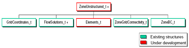
Unstructured Zone
Element Sections
NPE = NodePerElement(ElementType)
nelem = end - start + 1
   node(1,1),	  node(1,2)	 ... node(1,NPE)
   node(nelem,1), node(nelem,2), ... node(nelem,NPE)